
Technique for enhancing transistor performance by transistor specific contact design

a transistor and specific contact technology, applied in the direction of semiconductor devices, semiconductor/solid-state device details, electrical apparatus, etc., can solve the problems of affecting the overall transistor performance more intensively at the source side, and achieve the effect of increasing the contact resistance, reducing the overall contact resistance, and high fringing capacitan

Active Publication Date: 2008-10-30
TAIWAN SEMICON MFG CO LTD
View PDF10 Cites 16 Cited by
  • Summary
  • Abstract
  • Description
  • Claims
  • Application Information

AI Technical Summary

Benefits of technology

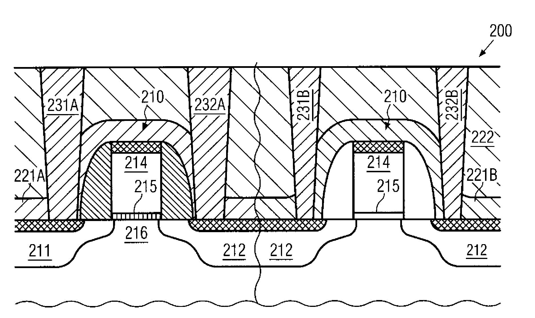
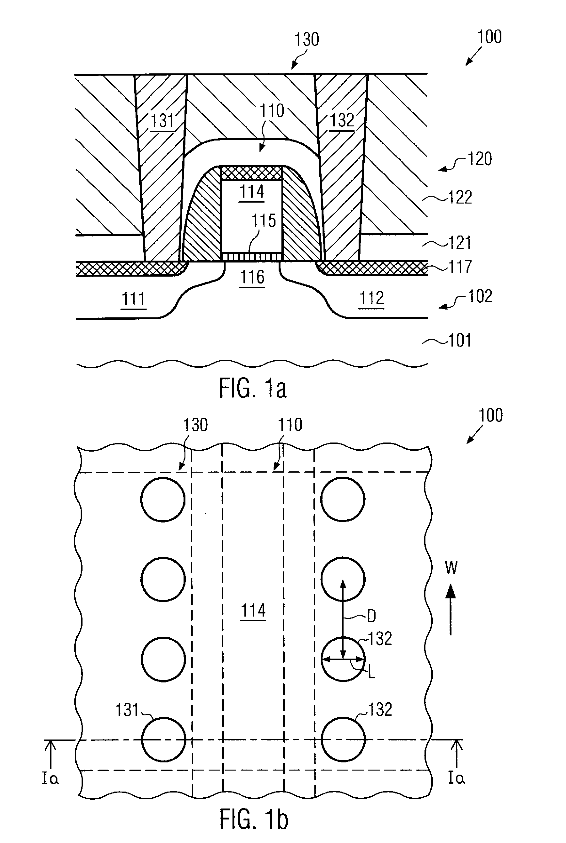
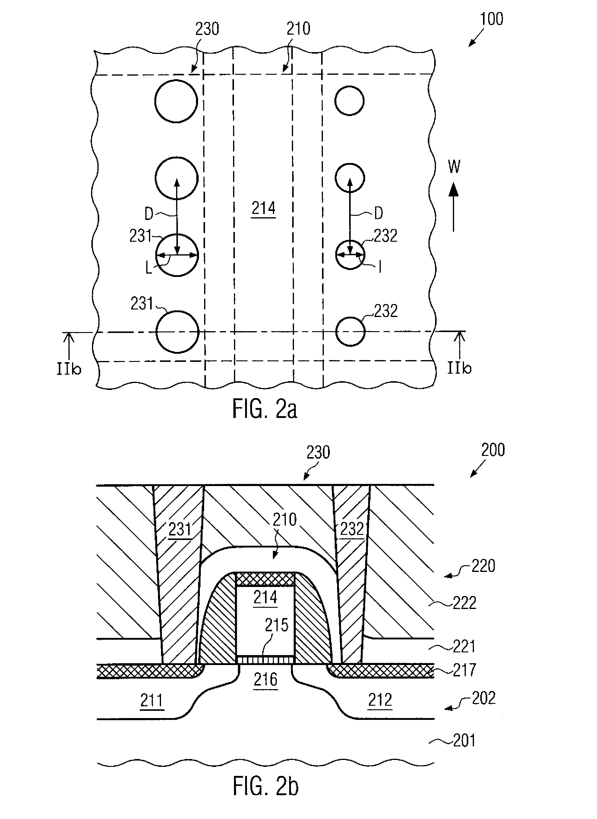
[0015]Generally, the subject matter disclosed herein relates to semiconductor devices and techniques for forming the same, in which the layout of contact structures in semiconductor devices may be locally varied in order to locally obtain specifically designed device characteristics. In this way, the mutual interaction between the contact structure and the respective circuit element may be adapted in a highly local manner, for instance, even within a single transistor element, in order to appropriately balance the advantage of a low ohmic contact with respect to negatively influencing other transistor characteristics, such as the strain-inducing mechanism, the generation of a high fringing capacitance and the like. For instance, in some cases, the stress relaxation caused by the contact elements with respect to a stressed dielectric material in the interlayer dielectric material may be more severe for P-channel transistors, since typically the compressive stress values obtained by presently available deposition techniques may be significantly higher compared to corresponding tensile stress values. On the other hand, the overall contact resistance is less critical for the P-channel transistor, since its intrinsic resistance, i.e., defined by the charge carrier mobility, is higher compared to the N-channel transistor. Consequently, an increase of the contact resistance may not necessarily negatively influence the overall series resistance, as the dominant factor may be the resistance of the highly doped semiconductor regions of the P-channel transistor, while at the same time an increased amount of strain may be induced in the respective channel regions. In other cases, it has been found that a voltage drop due to increased contact resistance may impact the overall transistor performance more intensively at the source side compared to the drain side. On the other hand, a capacitive coupling, and thus the fringing capacitance, between the drain contacts and the gate electrode may have a higher influence on the overall switching performance, since the drain side is typically the switching node of the transistor. Consequently, providing a reduced contact resistance at the drain side so as to reduce the fringing capacitance may be compensated for, or even overcompensated for, by a gain of switching performance, while reduced contact resistance at the source side results in enhanced transistor performance while not unduly affecting the switching behavior. Consequently, for otherwise identical design rules and process techniques, enhanced transistor performance may be obtained by locally varying the characteristics of the respective contact structures when taking into consideration locally varying influences on the operating behavior of the transistor when designing the contact structure.

Problems solved by technology

In other cases, it has been found that a voltage drop due to increased contact resistance may impact the overall transistor performance more intensively at the source side compared to the drain side.

Method used


Image

  • Technique for enhancing transistor performance by transistor specific contact design
  • Technique for enhancing transistor performance by transistor specific contact design
  • Technique for enhancing transistor performance by transistor specific contact design

Examples


Embodiment Construction

[0029]Various illustrative embodiments of the invention are described below. In the interest of clarity, not all features of an actual implementation are described in this specification. It will of course be appreciated that in the development of any such actual embodiment, numerous implementation-specific decisions must be made to achieve the developers' specific goals, such as compliance with system-related and business-related constraints, which will vary from one implementation to another. Moreover, it will be appreciated that such a development effort might be complex and time-consuming, but would nevertheless be a routine undertaking for those of ordinary skill in the art having the benefit of this disclosure.

[0030]The present subject matter will now be described with reference to the attached figures. Various structures, systems and devices are schematically depicted in the drawings for purposes of explanation only and so as to not obscure the present disclosure with details ...


PUM


Abstract

By locally adapting the size and / or density of a contact structure, for instance, within individual transistors or in a more global manner, the overall performance of advanced semiconductor devices may be increased. Hence, the mutual interaction between the contact structure and local device characteristics may be taken into consideration. On the other hand, a high degree of compatibility with conventional process strategies may be maintained.

Description

BACKGROUND OF THE INVENTION[0001]1. Field of the Invention[0002]The present disclosure generally relates to the fabrication of integrated circuits, and, more particularly, to the fabrication of highly sophisticated field effect transistors, such as MOS transistor structures, connected to a contact structure including a plurality of contact plugs.[0003]2. Description of the Related Art[0004]The manufacturing process for integrated circuits continues to improve in several ways, driven by the ongoing efforts to scale down the feature sizes of the individual circuit elements. Presently, and in the foreseeable future, the majority of integrated circuits are, and will be, based on silicon devices, due to the high availability of silicon substrates and due to the well-established process technology that has been developed over the past decades. A key issue in developing integrated circuits of increased packing density and enhanced performance has been the scaling of transistor elements, su...

Claims


Application Information

Patent Timeline
IPC IPC(8): H01L27/092
CPCH01L21/823807H01L21/823871H01L23/485H01L29/41758H01L29/665H01L29/6659H01L2924/0002H01L29/7833H01L29/7842H01L29/7843H01L2924/00H01L29/66469
Inventor GERHARDT, MARTINRICHTER, RALFFEUDEL, THOMASGRIEBENOW, UWE
Owner TAIWAN SEMICON MFG CO LTD
Learn More