
Hybrid carbon nanotube reinforced composite bodies

a carbon nanotube and composite body technology, applied in the field of composite materials, can solve the problems of high hardness, compressive strength and wear resistance, high toughness and impact strength, and achieve the effect of reducing the hardness and impact strength

Inactive Publication Date: 2008-09-04
SMITH INT INC
View PDF45 Cites 101 Cited by
  • Summary
  • Abstract
  • Description
  • Claims
  • Application Information

AI Technical Summary

Problems solved by technology

Generally, as the tungsten carbide particle size and / or cobalt content decrease, higher hardness, compressive strength, and wear resistance, but lower toughness is achieved.
Conversely, larger particle sizes and / or higher cobalt content yields high toughness and impact strength, but lower hardness.
On the other hand, fine grain powders, e.g., grains less than 5 μm, do not infiltrate satisfactorily.
Although the fracture toughness of cemented tungsten carbide has been somewhat improved over the years, it is still a limiting factor in demanding industrial applications such as high penetration drilling, where cemented tungsten carbide inserts often exhibit gross brittle fracture that can lead to catastrophic failure.
Bit bodies formed from either cast or macrocrystalline tungsten carbide or other hard metal matrix materials, while more erosion resistant than steel, lack toughness and strength, thus making them brittle and prone to cracking when subjected to impact and fatigue forces encountered during drilling.
This can result in one or more blades breaking off the bit causing a catastrophic premature bit failure.
Additionally, the braze joints between the matrix material and the PDC cutters may crack due to these same forces.
The formation and propagation of cracks in the matrix body and / or at the braze joints may result in the loss of one or more PDC cutters.
A lost cutter may abrade against the bit, causing further accelerated bit damage.
However, bits formed with sintered tungsten carbide may have sufficient toughness and strength for a particular application, but may lack other mechanical properties, such as erosion resistance.
Further, as the bulk particles used in ceramic materials decrease in size with the increasing use of nanoparticles (grain sizes less than 100 nm), observed brittleness has limited potential applications for the resulting material.
However, incorporation of the fibrous materials, such as carbon fibers, has presented difficulties including resistance to wetting of the fibers and reaction between the metal and carbide.

Method used


Image

  • Hybrid carbon nanotube reinforced composite bodies
  • Hybrid carbon nanotube reinforced composite bodies
  • Hybrid carbon nanotube reinforced composite bodies

Examples


Embodiment Construction

[0027]In one aspect, embodiments disclosed herein relate to composite or matrix bodies used in components of downhole cutting tools, including drill bits, mining picks, core bits, etc. In particular, embodiments relate to composite bodies having formed from tungsten carbide particles surrounded by a ductile metal matrix binder with a reinforcing nanotubular material.

[0028]In addition, embodiments of the present disclosure provide composite bodies which are formed from such tungsten carbides infiltrated by suitable metals or alloys as infiltration binders. Such a composite body may have high transverse rupture strength and toughness while maintaining wear and erosion resistance. Embodiments of the present disclosure are based, in part, on the determination that the life of a composite bit body is related to the body's strength (also known as transverse rupture strength), toughness, and resistance to erosion.

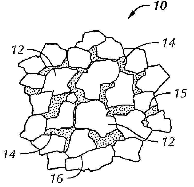
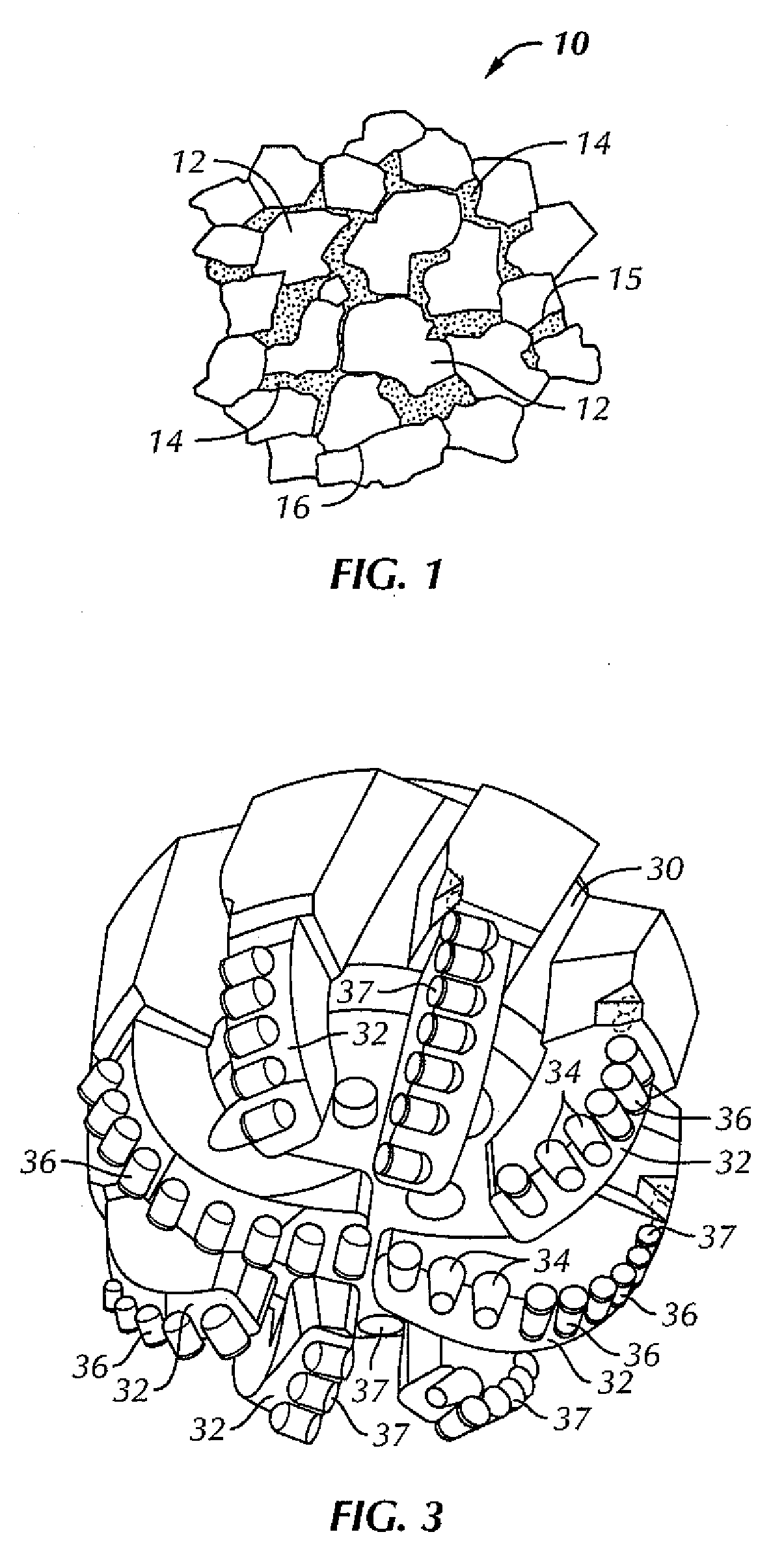
[0029]FIG. 1 illustrates the conventional microstructure of cemented tungsten...


PUM

PropertyMeasurementUnit
thicknessaaaaaaaaaa
grain sizesaaaaaaaaaa
diameteraaaaaaaaaa

Abstract

A composite body for cutting tools that includes a ductile phase; a plurality of carbide particles dispersed the ductile phase; and a plurality of nanotubes integrated into the composite body is disclosed. Methods of making such composite bodies and drill bits formed of such material are also disclosed.

Description

CROSS-REFERENCE TO RELATED APPLICATIONS[0001]This application, pursuant to 35 U.S.C. § 119(e), claims the benefit of U.S. Patent Application No. 60 / 858,830 filed on Nov. 14, 2006, and U.S. Patent Application No. 60 / 917,163 filed on May 10, 2007, both of which are incorporated by reference in their entiretyBACKGROUND OF INVENTION[0002]1. Field of the Invention[0003]Embodiments disclosed herein relate generally to composite materials used in cutting tools.[0004]2. Background Art[0005]Historically, there have been two types of drill bits used drilling earth formations, drag bits and roller cone bits. Roller cone bits include one or more roller cones rotatably mounted to the bit body. These roller cones have a plurality of cutting elements attached thereto that crush, gouge, and scrape rock at the bottom of a hole being drilled. Several types of roller cone drill bits are available for drilling wellbores through earth formations, including insert bits (e.g. tungsten carbide insert bit, ...

Claims


Application Information

Patent Timeline
Patent Type & Authority Applications(United States)
IPC IPC(8): E21B10/46
CPCB22F1/0025B22F2005/001C23C30/005C22C26/00C22C29/06B82Y30/00B22F1/0547
Inventor ZHANG, YOUHEZHAN, GUODONGSHENG, XIAYANGLOCKSTEDT, ALAN W.SHEN, YUELINDENG, HONGGRIFFO, ANTHONYKESHAVAN, MADAPUSI K.
Owner SMITH INT INC
Learn More