Method for fabricating magnetic write pole for a magnetic head using an E-beam resist mask

a write pole and magnetic head technology, applied in the manufacture of head surfaces, instruments, record information storage, etc., can solve the problems of complicated photolithographic techniques and even more challenging problems, and achieve the effect of accurately establishing the track width and accurately fabricating the pole tip track width

Inactive Publication Date: 2008-06-05
WESTERN DIGITAL TECH INC
View PDF13 Cites 6 Cited by
  • Summary
  • Abstract
  • Description
  • Claims
  • Application Information

AI Technical Summary

Benefits of technology

[0008]The present invention is a method for accurately fabricating the pole tip track width while independently controlling track width and bevel angle of the pole tip. The method includes accurately establishing the track width in a portion of the pole tip material using an epoxy resist such as KMPR with E-beam exposure fabrication techniques. This pole tip portion having the established track width is then protected with a temporary masking material, while an unprotected pole tip portion is left exposed to be shaped. The unprotected portion is then milled to produce beveled side walls, while the protected portion includes the narrow track width trailing edge. Also disclosed is a magnetic head having a pole tip of the present invention, and a disk drive having the magnetic head.
[0010]It is another advantage of the method for fabricating a magnetic head of the present invention that track width of the write pole tip can be made smaller while retaining pole tip fabrication accuracy.

Problems solved by technology

Making reliable components of such microscopic size has been a challenge to the fabricating process arts.
This problem is made even more challenging because the pole tip shape at the air bearing surface (ABS) of the magnetic head is preferably not a simple rectangle, but is trapezoidal, with parallel top and bottom edges, and with a bevel angle preferably of approximately 5 to 15 degrees on the side edges.
Such photolithographic techniques are quite complicated, involving two or three layers of photoresist materials and masks to achieve acceptable results.

Method used


Image

  • Method for fabricating magnetic write pole for a magnetic head using an E-beam resist mask
  • Method for fabricating magnetic write pole for a magnetic head using an E-beam resist mask
  • Method for fabricating magnetic write pole for a magnetic head using an E-beam resist mask

Examples


Embodiment Construction

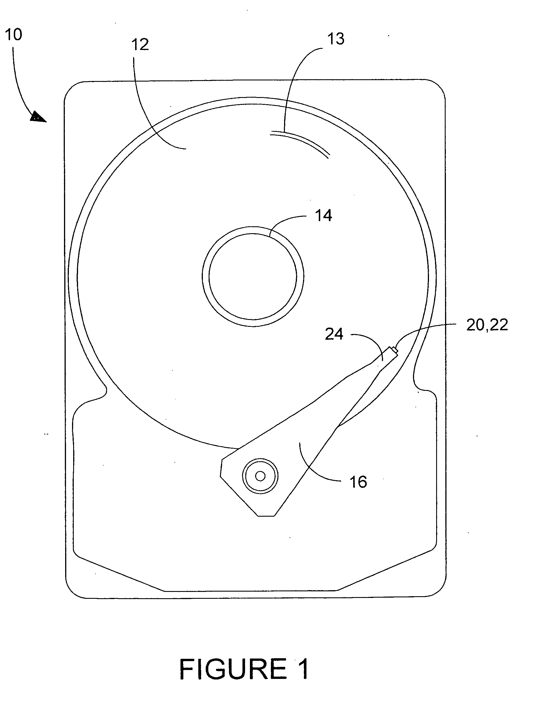
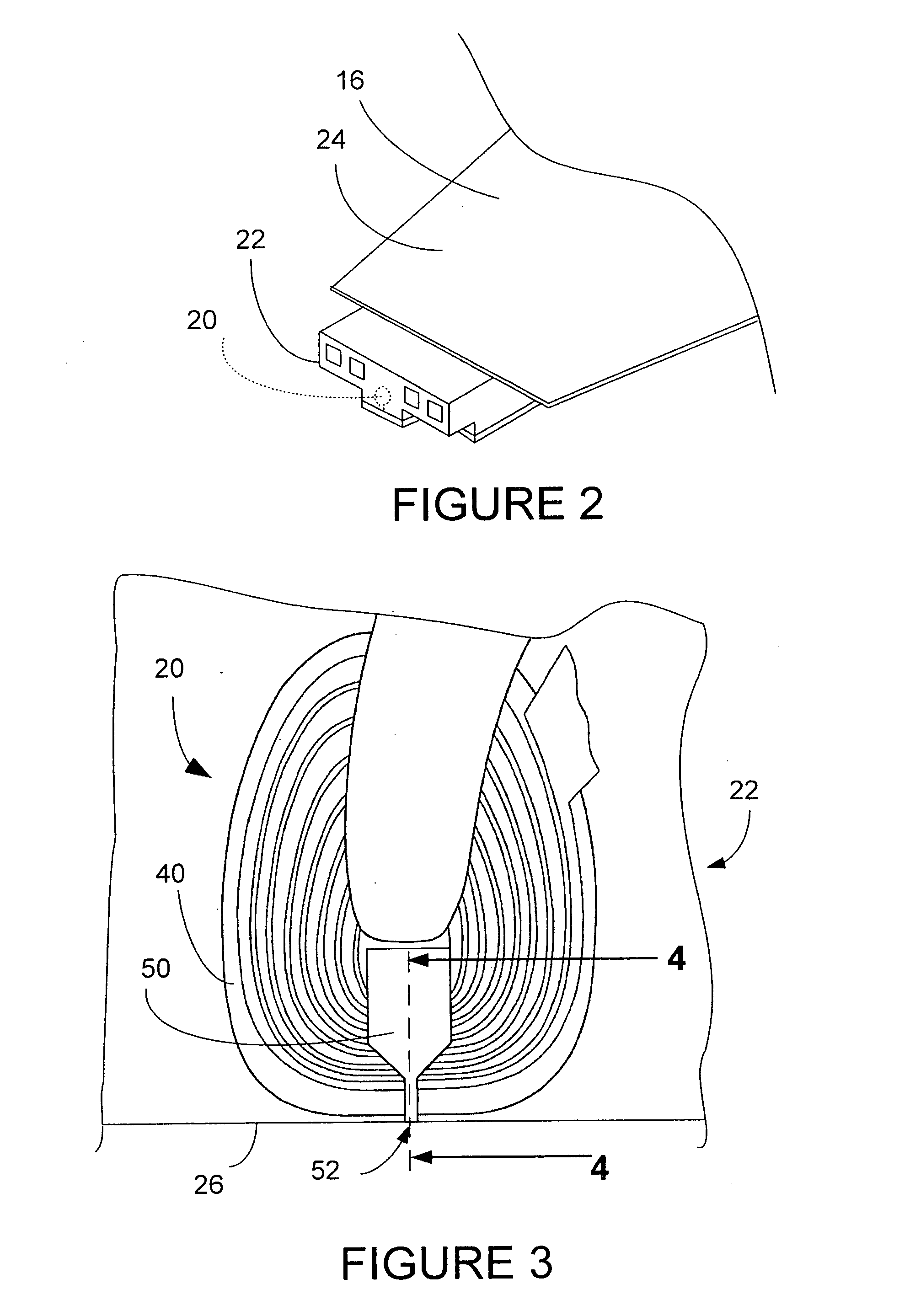
[0019]FIG. 1 is a top plan view that depicts significant components of a hard disk drive which includes the magnetic head of the present invention. The hard disk drive 10 includes a magnetic media hard disk 12 having a plurality of data tracks 13 that is rotatably mounted upon a motorized spindle 14. An actuator arm 16 is pivotally mounted within the hard disk drive 10, and a magnetic head 20 of the present invention is fabricated upon a slider 22 that is disposed upon a distal end 24 of the actuator arm 16. A typical hard disk drive 10 may include a plurality of disks 12 that are rotatably mounted upon the spindle 14 and a plurality of actuator arms 16, each having one or more magnetic heads 20 mounted upon the distal end 24 of the actuator arm. As is well known to those skilled in the art, when the hard disk drive 10 is operated, the hard disk 12 rotates upon the spindle 14 and the slider 22 acts as an air bearing that is adapted for flying above the surface of the rotating disk. ...


PUM

PropertyMeasurementUnit
Thicknessaaaaaaaaaa
Thicknessaaaaaaaaaa
Thicknessaaaaaaaaaa

Abstract

A method is disclosed for independently controlling track width and bevel angle of a write pole tip of a magnetic recording head. The method includes establishing the track width in the pole tip layer material utilizing E-beam lithography. A portion of this pole tip material having the established track width is protected by providing a temporary masking material to make a protected portion. At least one unprotected portion is left exposed to be shaped. This unprotected portion is then beveled to produce at least one beveled portion. The protected portion produces an upper pole tip portion which together with the beveled portion produce an improved pole tip. Also disclosed is a magnetic head having the improved pole tip, and a disk drive having a magnetic head having the improved pole tip.

Description

BACKGROUND OF THE INVENTION[0001]1. Field of the Invention[0002]The present invention relates generally to the manufacture of magnetic heads for data storage devices and more specifically to the fabrication of a narrow track width write pole tip for a magnetic head for a hard disk drive.[0003]2. Description of the Prior Art[0004]Data is conventionally written by a magnetic head and stored in a thin magnetic media layer of a hard drive disk. A typical magnetic recording head includes a trailing magnetic write pole, a leading return or opposing magnetic pole that is magnetically coupled to the write pole, and an electrically conductive induction coil disposed proximate the write pole and opposing pole. Current is passed through the induction coil to create magnetic flux within the write pole. The magnetic flux passes from the write pole tip, through the magnetic recording layer, and across to the opposing pole. Magnetization transitions on the magnetic layer of the recording disk are ...

Claims


Application Information

Patent Timeline
IPC IPC(8): G11B5/127
CPCG11B5/127G11B5/3116G11B5/3163Y10T29/49046Y10T29/49043Y10T29/49052Y10T29/49041Y10T29/49021
Inventor LEE, KIM Y.LO, JYH-SHUEY
Owner WESTERN DIGITAL TECH INC
Why Eureka
Try Eureka