
Apparatus, Systems and Methods for Work Piece Isothermal Dry Machining and Assembly Fixtures

a technology of isothermal dry machining and apparatus, applied in the field of apparatus, systems and methods for work piece isothermal dry machining and assembly fixtures, can solve the problems of affecting the quality of work piece, the inability to hold rigidly, accurately and inexpensively, and the inability to accurately and accurately predict the type of work piece, etc., to achieve the effect of reducing the cost of assembling, installing and operating the inventive system, and increasing productivity

Active Publication Date: 2008-05-15
JENSEN ROBERT M
View PDF23 Cites 7 Cited by
  • Summary
  • Abstract
  • Description
  • Claims
  • Application Information

AI Technical Summary

Benefits of technology

[0035]As a result, the inventive system permits the machine to take deeper depths of cut at faster speeds thereby reducing both cycle times and costs. By increasing rigidity and accuracy, the inventive system also enhances work piece dimensional accuracy and overall repeatability of the machining operation. This increases individual work piece quality and multi-same-piece run consistency. The inventive isothermal, work piece holding system allows machining the work piece to meet or exceed dimensional tolerance every time. Another advantage of the invention is that it is the most effective method to cut production costs and is the most reliable path to providing the lowest possible cost production method.
[0036]Another advantage of the invention is that it maintains the temperature of the work piece constant (isothermal) during machining. This prevents thermally induced TCE variations, arising from all possible sources, from affecting the work piece, pushing it outside the limits of permitted dimensional tolerance(s). The invention is straight forward, in that it fits within the currently in-place machine tool industry without complex, special order, unavailable components. One skilled in this art can readily understand that the components of the inventive system have been individually proven in the context of other uses, and are commercially available. In addition, the cost of assembling, installing and operating the inventive system is minimal compared to the cost of a large expensive reject work piece.
[0037]The inventive system is effectively immediately operational upon installation. Upon start up of machining of a new design or new configuration of work piece, there is an initial self-“tuning period” of the inventive system. In this tuning period, a single, temporary temperature rise of 3-5° F. above the desired isothermal baseline temperature of the work piece is allowed to occur so that the controller can quantify and map the thermal response of this type of work piece for the particular machining process that is being done on it. Since the initial cuts are for roughing out the piece, accompanying TCE changes in work piece dimensions are not significant or relevant to the follow-on precision stages of machining.
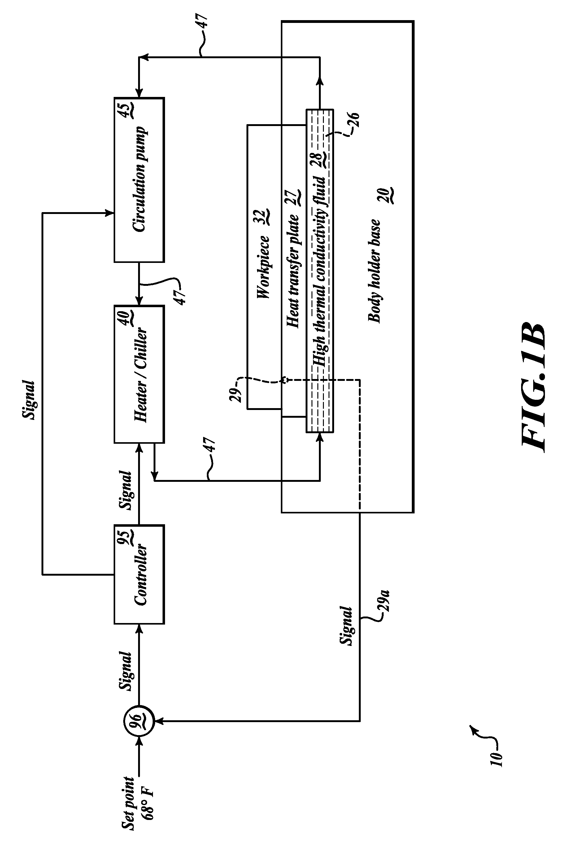
[0038]Once the configuration is tuned through a single work piece, it is not necessary to subject subsequent similar or identical work pieces to each go through an initial tuning step. The MPC's CPU receives thermal profile data as the cutting progresses and this data is used to map the thermal response, the results of which are one of the inputs to the MPC database and applications program algorithm that controls the coolant system operation, e.g., pump cycling and coolant fluid volumetric flow to maintain the work piece at isothermal conditions. Thereafter, in normal operation, the controller of the inventive system continuously adapts to all changes required to maintain the work piece temperature, such as when the cutters progressively become dull. This self-tuning process does not interrupt production, so productivity is increased.
[0039]Although the description below relates by way of example to a 3-axis machine, it should be understood that the inventive system is easily adapted to a 5-axis system in which the work piece can be rotated in at least 2 axes. In addition, while the inventive system is described, by example, as utilizing a single temperature sensor touching the work piece for direct temperature measurement with its signal being sent to the controller as fully representative of the thermal profile of the entire work piece (a single temperature in-put permits use of a simple control system), multiple temperature sensors, or sensors other than contact resistive temperature devices (RTD) or thermocouples, can be used, and may be preferred for some work piece configurations.
[0040]Another advantage of the invention is that it is readily extendible to three dimensions and any group of holding body shapes that may be necessary or desired to hold similar work pieces. The inventive system can be quickly constructed in days, instead of the multiple-week lead-time currently required to construct large, complex aluminum or steel fixtures as work holders for large parts. Another advantage is that the cutter tooling will last longer since the sharp edges of the tools are not being battered by exposure to constant chatter. All the advantages of the inventive system cumulatively eliminate the need for manually reworking an unacceptable (reject) work piece back into surface finish specification and elimination of an additional, re-inspection step. Further objects and advantages of this invention will become apparent from a consideration of the drawings and related description.

Problems solved by technology

These types of work pieces are very difficult to hold rigidly, accurately and inexpensively because they are inherently susceptible to chatter.
Stress concentrations can initiate both stress corrosion cracking and corrosion-fatigue in the presence of an atmospheric corrodent.
Corrosion-induced fatigue can also cause a somewhat similar fracture mechanism which causes progressive cracking due to cyclic stress loading during service.
Either fracture mechanism can lead to catastrophic failure of a work piece in normal service.
None provide vibration damping of thin cross-section work pieces or temperature control of the work piece.
Attempts to use elastic materials rely on partial compression of a compliant material, resulting in a lack of rigidity in supporting the work piece.
However, at best, only 75% of the heat energy is exported in the chips.
Due to the deficiencies of such prior anti-chatter work piece holding methods, significant quantities of reject work pieces are created, requiring costly, manual rework with poor results.
The aerospace industry dry machines work pieces because they are too large to machine “wet”.
This new specification presents a two fold problem: First, the machine tool itself must be much more accurate and repeatable.
At present, this new quality specification is unmet by original equipment manufacturing (OEM) vendors of structural frame components.
These issues are exacerbated by the aircraft industry's adoption of higher strength, Alcoa 7075-B alloy, since chatter problems may make the most efficient machining of the high strength Al alloy slower, while machining, heat-induced TCE would make precision impossible.
Thus, there remains a severe, urgent, un-met need in the art to provide a solution to the serious and costly problems of dry cutter friction driving TCE-induced expansion of the work piece, and cutter / work piece interaction chatter that results in work-piece surface finish irregularities and off-specification dimensional errors.

Method used


Image

  • Apparatus, Systems and Methods for Work Piece Isothermal Dry Machining and Assembly Fixtures
  • Apparatus, Systems and Methods for Work Piece Isothermal Dry Machining and Assembly Fixtures
  • Apparatus, Systems and Methods for Work Piece Isothermal Dry Machining and Assembly Fixtures

Examples


first embodiment

, Machining Flat and Complex Work Pieces

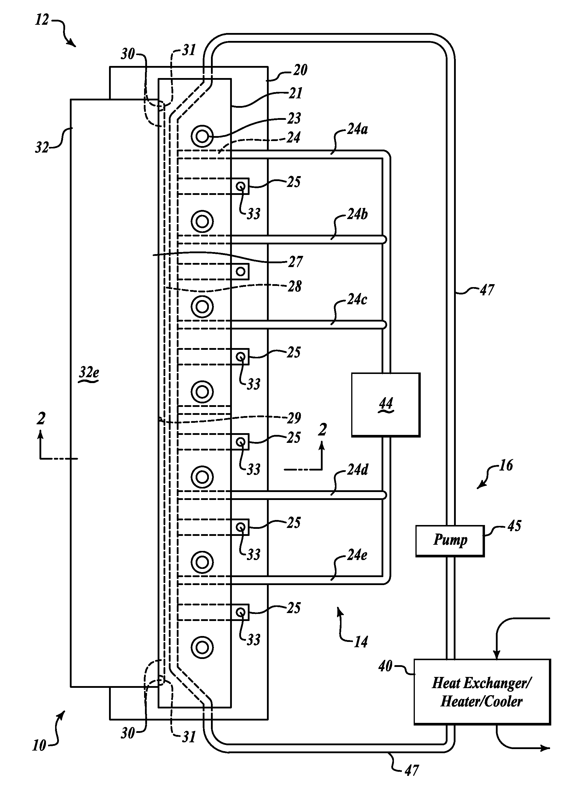
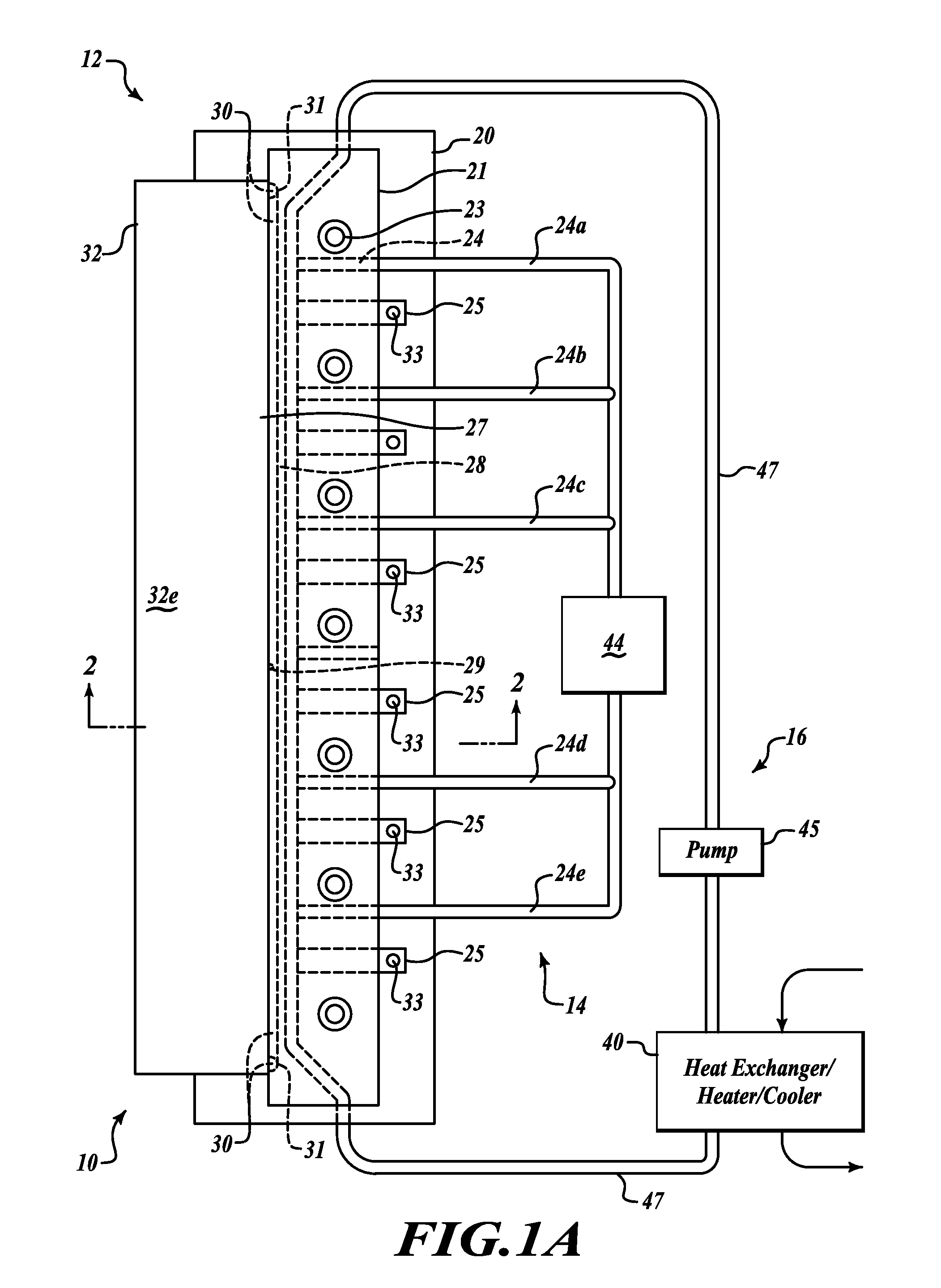
[0059]FIGS. 1A, 1B and 2 show the inventive work piece holding system apparatus 10 holding an inverted L-shaped work piece 32 in a vertical orientation for machining (milling machine and tooling cutter are not shown). The inventive system includes holding body assembly 12, vacuum / mechanical clamping system 14 and closed loop thermal control system 16.

[0060]The holding body assembly 12 includes base body 20 disposed to rest on and be secured to a movable or stationary bed of a milling machine 71 by bolts 102 with the work piece 32 standing on its leg portion 32a by its dove-tail end 32b. End 32b is retained by dove-tail clamp 25 secured to the base body by bolt 33. The holding body 21 and body extension 22 are matingly aligned one above the other and abut against face 32c of the leg portion 32b. Depending on the configuration of the work piece, the extension may be in multiple pieces, with the body being 20, while both 21 and 22 are extensions....

second embodiment

, Application to Machining and Assembling Aerospace Wing Spars

[0077]In this second embodiment of the invention, as step one (referring to FIGS. 1-4), all the work pieces, including the wing spar chords 50 and the wing webs 52, are consistently machined by the inventive vibration damping, isothermal work piece holding system.

[0078]In FIGS. 5 and 6, an inventive holding system is configured as an isothermal assembly fixture to maintain accurate mechanical alignment of each individual web 52 to spar chords 50a, 50b and the rib posts 51 with flanges 51a, while the temporary fasteners 54 are automatically installed by an automated rivet machine (not shown). Fewer than the usual number of temporary fasteners 54 are tensioned to hold the posts to the web and spars. Note the spar chords 50 a, b and the web 52 are secured by the vacuum channels, and cooled by the thermal cooling system 26, 27 in the upper and lower work piece holding bodies 21U, 21L and the moveable work piece back supports ...

third embodiment

, Application to Manufacture of Aircraft Skin Panels

[0087]By way of background, historically, aircraft wings are assembled by fastening large, flexible, contoured exterior panels (called skins) to stringers by rivets. The whole operation is performed in three distinct stages.[0088]In Stage 1, all the work pieces are manually loaded onto a work fixture, which holds all work pieces in approximate relative alignment, within ±0.030 of an inch on the Y axis and ±0.060 of an inch on the X axis. Assembly workers then manually drill holes to install the first 10-15% of all fasteners for emplacement of temporary fasteners (called tack fasteners) to attach each stringer to the wing skin.[0089]During stage 2, the automated assembly operation begins. An automated rivet machine which utilizes a vision guidance system finds the location of a first tack fastener on the outside of the skin. The rivet machine uses this location as a reference point to adjust the position for drilling holes for the p...


PUM

PropertyMeasurementUnit
Timeaaaaaaaaaa
Temperatureaaaaaaaaaa
Timeaaaaaaaaaa

Abstract

Isothermal work piece holding system uses vibration-damping, low thermal conductivity, low TCE polymer-composite holding body(ies) to damp machine tool vibration and chatter while accurately, rigidly maintaining the work piece in position by vacuum and / or mechanical clamps during machining. Cooling fluid channels having high thermal conductivity plates in contact with the work piece transfer thermal energy to / from it to maintain it isothermal during machining, inspection and assembly, eliminating dimensional changes and increasing process repeatability. Minimizing chatter reduces cycle time and improves surface finish which eliminates manual re-work. The system employs vacuum and coolant fluid pumps, heater / cooler(s), temperature sensor(s) and controller(s) to achieve highly accurate dimensional tolerances machining of parts which reduces error stack-up and assembly costs. Isothermal fixtures are disclosed for assembling parts and automated rivet settings in precise locations with reduced use of shims. The inventive isothermal system is applicable to control of TCE / I2R effects in linear induction motors.

Description

CROSS REFERENCE TO RELATED CASE[0001]This is the Regular U.S. Patent Application of Provisional Application Ser. No. 60 / 865,537 filed Nov. 13, 2006 by the same inventor and entitled Apparatus, Systems, and Methods for Isothermal, Vibration Damping, Dry Machining Work Piece Holding System, the benefit of the filing date of which is claimed under 35 USC 119 ff, and the disclosure of which is incorporated by reference herein.FIELD[0002]The present invention relates to holders for work pieces being machined, primarily in dry machining processes, and more specifically to apparatus, automatic control systems and methods of continuously attenuating high frequency vibrations and preventing heat build-up, in large, thin cross-section, contoured and / or complex shape or multi-part work pieces, while simultaneously maintaining the work pieces isothermally stable during a machining and / or an inspection operation. The inventive isothermal work piece holding systems reduce machining errors arising...

Claims


Application Information

Patent Timeline
IPC IPC(8): B25B11/00
CPCB23Q11/141B23Q11/143Y10T29/49998B23Q3/088B25B11/005B23Q1/28B23Q3/02B23Q5/28B25B11/00
Inventor JENSEN, ROBERT M.
Owner JENSEN ROBERT M
Learn More