Eureka AIR delivers breakthrough ideas for toughest innovation challenges, trusted by R&D personnel around the world.

Method and apparatus for forming nano-particles

a nano-particle and nano-particle technology, applied in lighting and heating apparatus, muffle furnaces, furnaces, etc., can solve the problems of uniform particle size and surface finish, and the granular form is often the least uniform, so as to reduce the cost of raw materials and manufacturing unit cost, the effect of less expensiv

Inactive Publication Date: 2008-05-08
BRICOLEUR PARTNERS LP
View PDF4 Cites 35 Cited by
  • Summary
  • Abstract
  • Description
  • Claims
  • Application Information

AI Technical Summary

Benefits of technology

[0008]An aspect of at least one of the embodiments disclosed herein includes the realization that granular raw materials are typically significantly less expensive than the same material in other forms. For example, many metals are available in granular, extruded wire, bar, rod, and other forms. Of these forms, the granular form is often the least expensive, by a significant margin. However, the granular form is often the least uniform in terms of particle size and surface finish. For example, for many metals, the granular form usually has uneven outer surfaces, and a wide spread of outer diameter sizes that can include particles generally larger than the nano-scale, often times measured on the micron scale and particles as large as fractions of an inch. A system or method that can transform such granular raw material can benefit from the lower raw material cost, resulting in a lower unit cost of manufacturing the resulting nano-scale particles.
[0016]Another aspect of at least one of the embodiments disclosed herein includes the realization that cycling the temperature of a heater, such as a heater used for vaporizing a raw material, can reduce or prevent problems associated with feeding raw material into contact with such a heater. For example, but without limitation, some raw materials can bounce off of a heater that is at or above the vaporization temperature of the raw material. However, if the temperature of the heater is lowered below the temperature that causes such bouncing, some materials can more readily stick to and melt on the heater. Afterwards, the heater temperature can be raised to a temperature appropriate for vaporization.
[0019]Another aspect of at least one of the embodiments disclosed herein includes the realization that a feeder device of a nano-scale particle generator can be improved by incorporating a metering device comprising a moveable receptacle. For example, but without limitation, when generating nano-scale particles from a granular raw material, the metering of such a material can be difficult because of the nature of such typical granular raw materials; such particles usually have uneven outer surfaces and can have a widely ranging particle size distribution. By using a metering device having a moveable receptacle, a desired volume of raw material can be accurately delivered periodically, thereby reducing the likelihood of waste.

Problems solved by technology

However, the granular form is often the least uniform in terms of particle size and surface finish.

Method used


Image

  • Method and apparatus for forming nano-particles
  • Method and apparatus for forming nano-particles
  • Method and apparatus for forming nano-particles

Examples


Embodiment Construction

[0043]The following description and examples illustrate preferred embodiments of the present inventions in detail. Those of skill in the art will recognize that there are numerous variations and modifications of these inventions that are encompassed by its scope. Accordingly, the description of preferred embodiments should not be deemed to limit the scope of the present inventions.

[0044]“Quench gas” or “quenchant gas” as used in this specification refers to a gas that has a cooling effect on a material and may, depending upon the ambient conditions, induce a phase change in the material. As used within this specification, the term “substantially laminar” includes generally smooth fluid flows that may be completely laminar as well as flows that include turbulent portions, as described and illustrated below, and flows including incidental or transient eddies. The term “substantially free convection,” as used in this specification, includes movement of fluids (including gases) due to e...


PUM

PropertyMeasurementUnit
temperatureaaaaaaaaaa
heightaaaaaaaaaa

Abstract

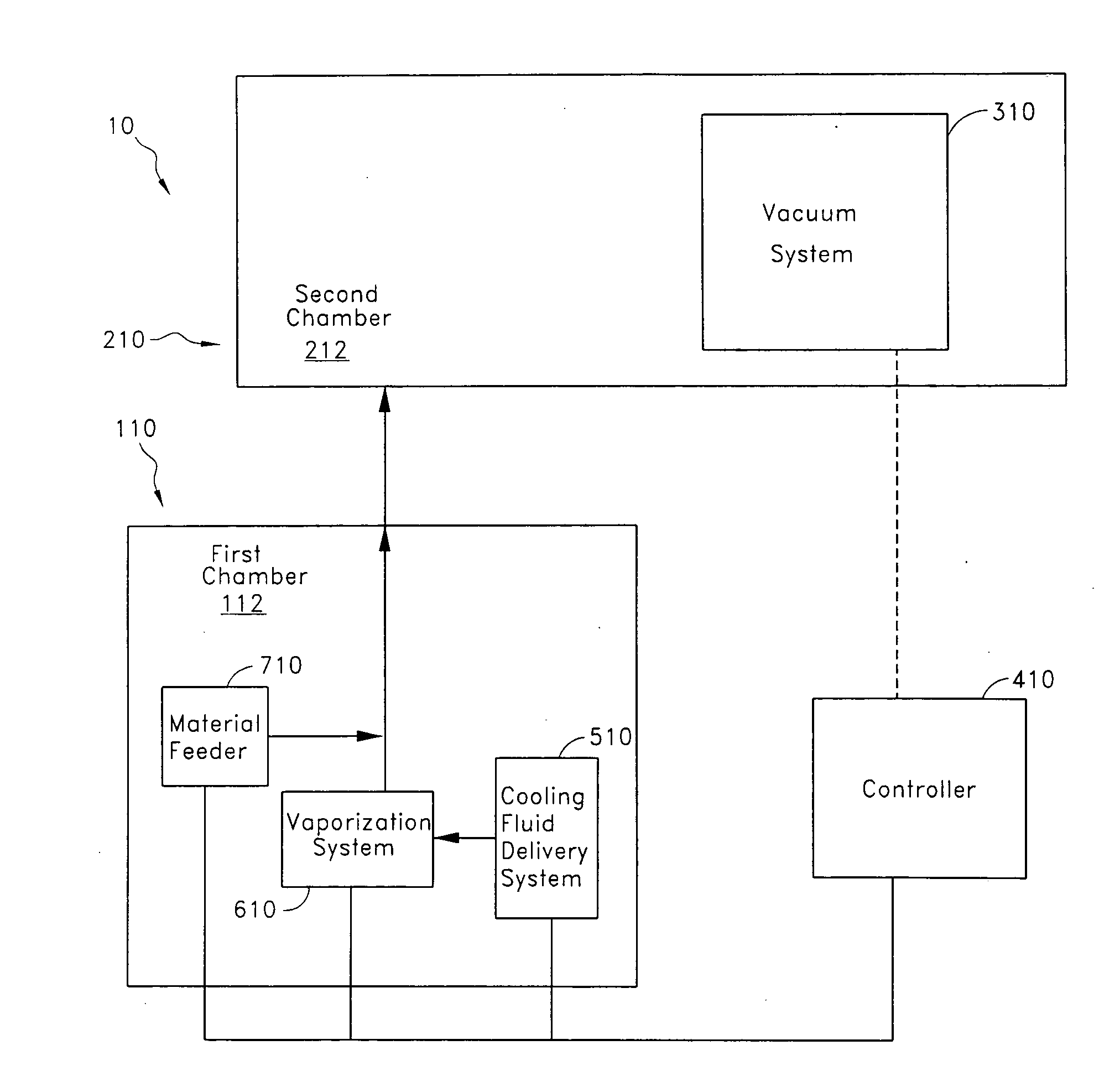
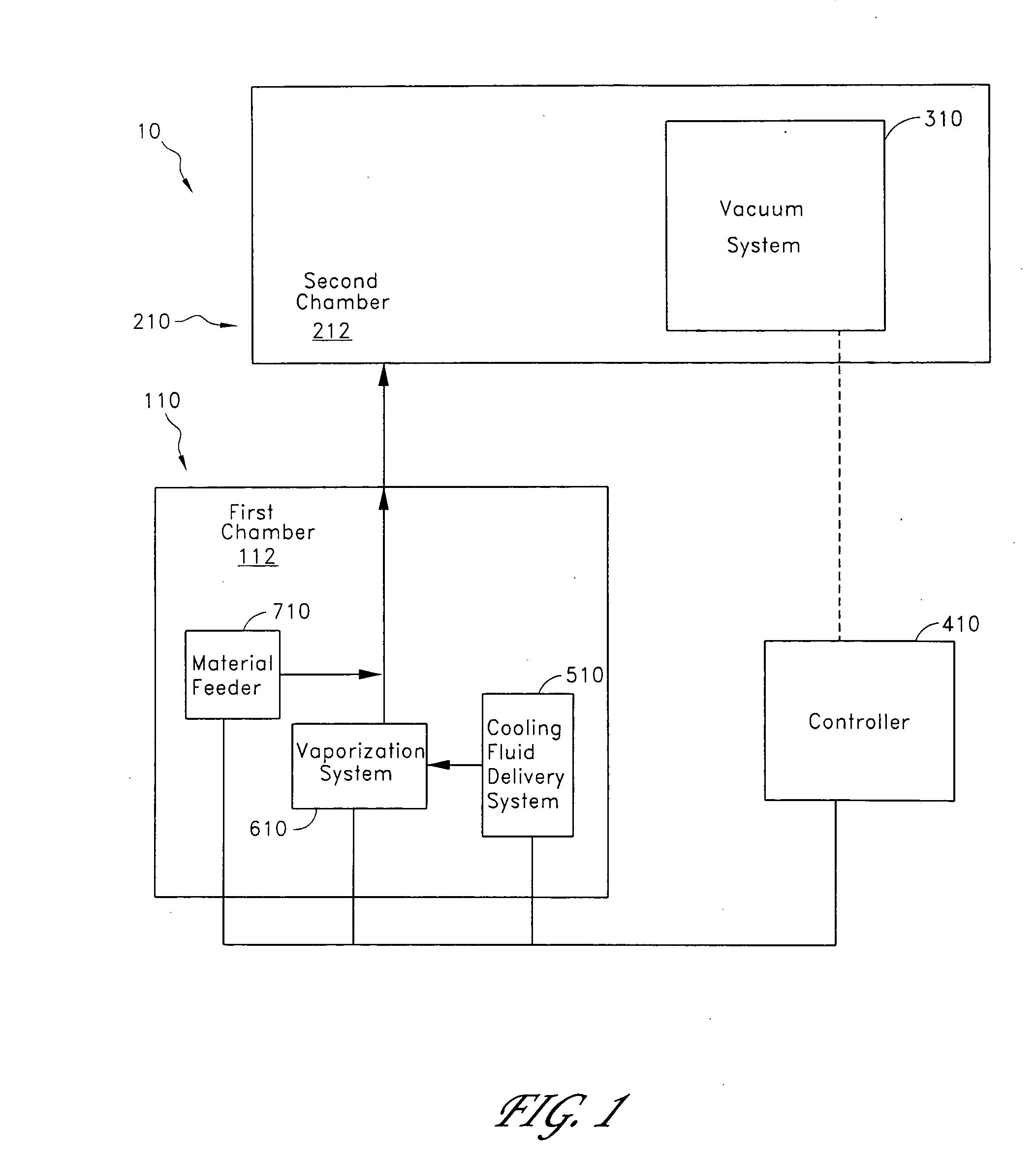
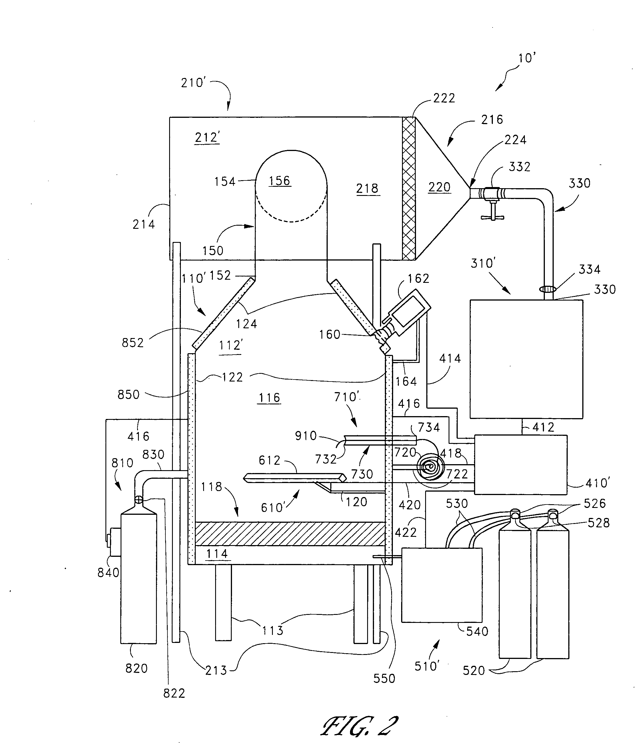
Nano-scale particles of materials can be produced by vaporizing material and allowing the material to flow in a non-violently turbulent manner into thermal communication with a cooling fluid, thereby forming small particles of the material that can be in the nano-scale size range. A raw material feeder can be configured to feed raw material toward a heater which vaporizes the raw material. The feeder can include a metering device for controlling the flow of raw material toward the heater. A gas source can also be used to cause gas to flow through a portion of the raw material feeder along with the raw material.

Description

BACKGROUND OF THE INVENTIONS[0001]1. Field of the Inventions[0002]The inventions disclosed herein relate to the production of nano-sized particles. More particularly, the inventions relate to the handling of raw material, the vaporization, condensation, and formation of nano-sized particles as well as for the handling of nano-scale particles after formation.[0003]2. Description of the Related Art[0004]Techniques for producing nano-particles generally fall into one of three categories, namely: mechanical, chemical or thermal processing. In mechanical processes, nanopowders are commonly made by crushing techniques such as ball milling. There are several disadvantages to this approach. The grinding media and the mill wear away and combine with the nanomaterial, contaminating the final product. Additionally, nano-particles produced by ball milling tend to be non-uniform in size and shape and have a wide distribution of particle sizes.[0005]Chemical processes can be used to create nanoma...

Claims


Application Information

Patent Timeline
Patent Type & Authority Applications(United States)
IPC IPC(8): F27B14/00
CPCB22F9/082B22F2998/00F27B5/04F27B5/14B29C35/02F27B5/18B82Y40/00B22F1/0018B22F1/054
Inventor CARPENTER, RAY DOUGLAS
Owner BRICOLEUR PARTNERS LP
Why Eureka
Eureka Blog
Learn More