
Light-harvesting antennae for organic solar cells

a solar cell and organic technology, applied in the field of photovoltaic cells, can solve the problems of poor fundamental understanding of the physics that underlies the various processes of low conversion efficiency, and inability to replicate the complex pigment/protein interactions of photosynthetic proteins used in man-made solar light harvesting devices, etc., to improve the efficiency of incident spectra, improve the efficiency of solar cells, and improve the effect of energy conversion efficiency

Inactive Publication Date: 2008-04-17
SCHOLES GREGORY DENTON +2
View PDF1 Cites 38 Cited by
  • Summary
  • Abstract
  • Description
  • Claims
  • Application Information

AI Technical Summary

Benefits of technology

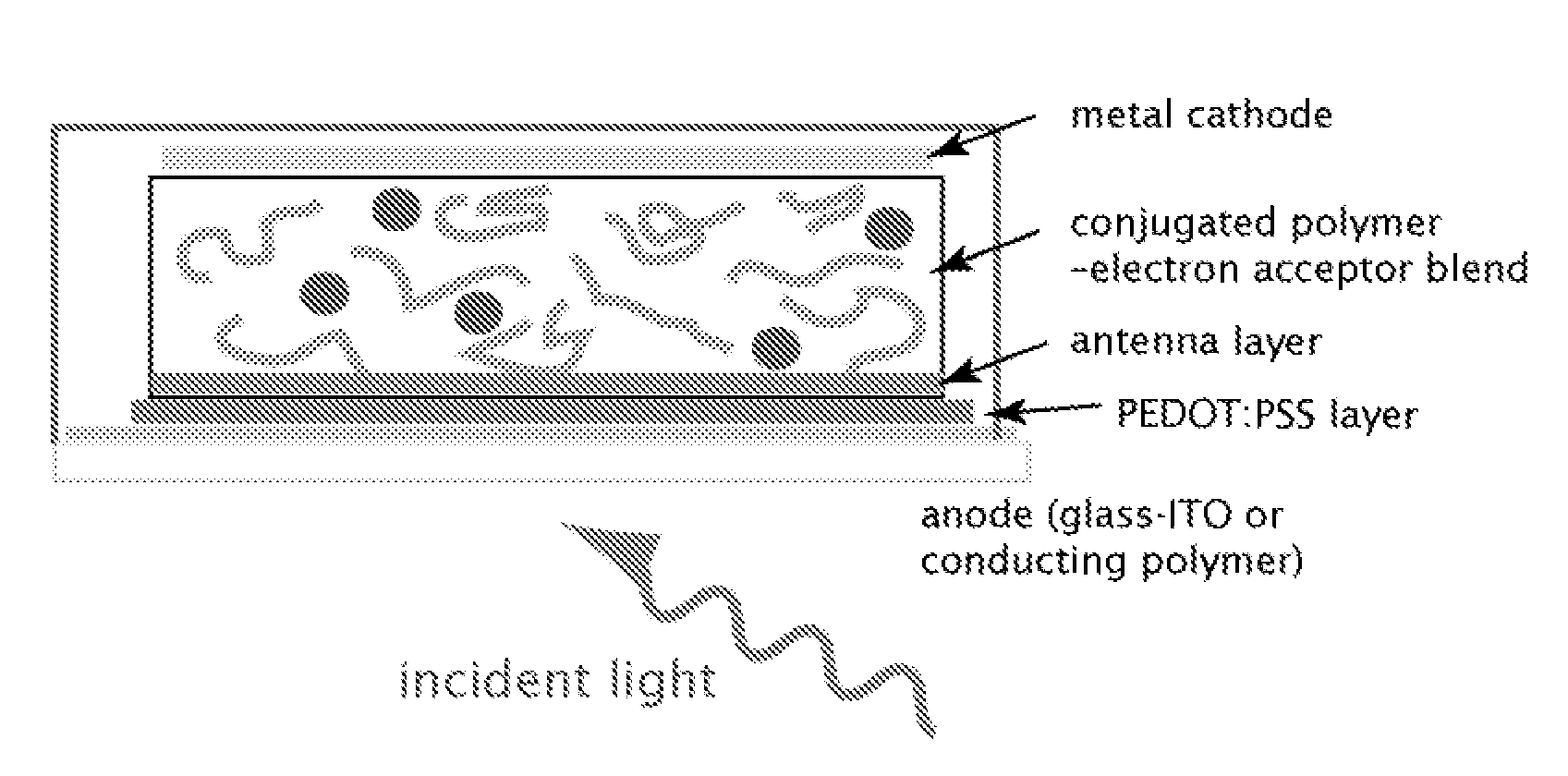
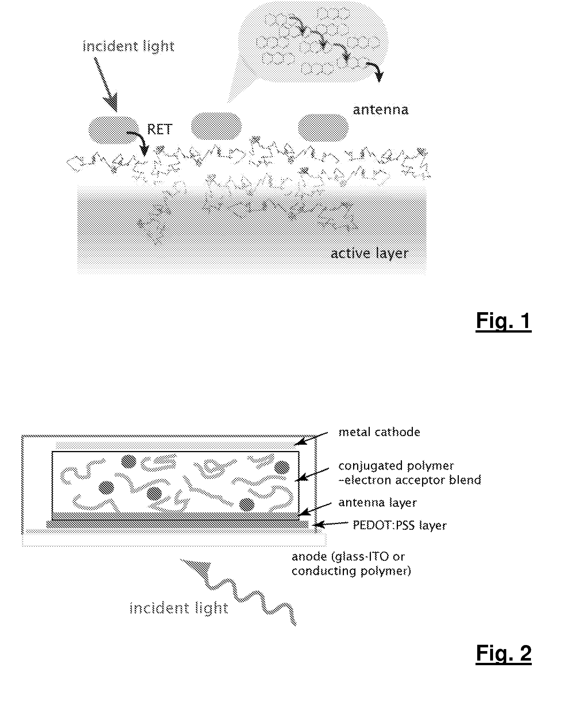
[0019] In an aspect of the present invention, an antenna may be a cluster, microcrystal, or film of molecules that harvests light and transfers the captured excitation energy to an active layer of a solar cell device using resonance energy transfer (“RET”), wherein the charge separation and / or the formation of free carriers takes place. The antenna may be either in direct contact with the active layer or it may be external to a contact and connected by an intermediary, e.g., via a metal electrode. The molecular aggregate of the antenna layer increases both the effectiveness of light absorption as well as the efficiency of RET to the active layer.
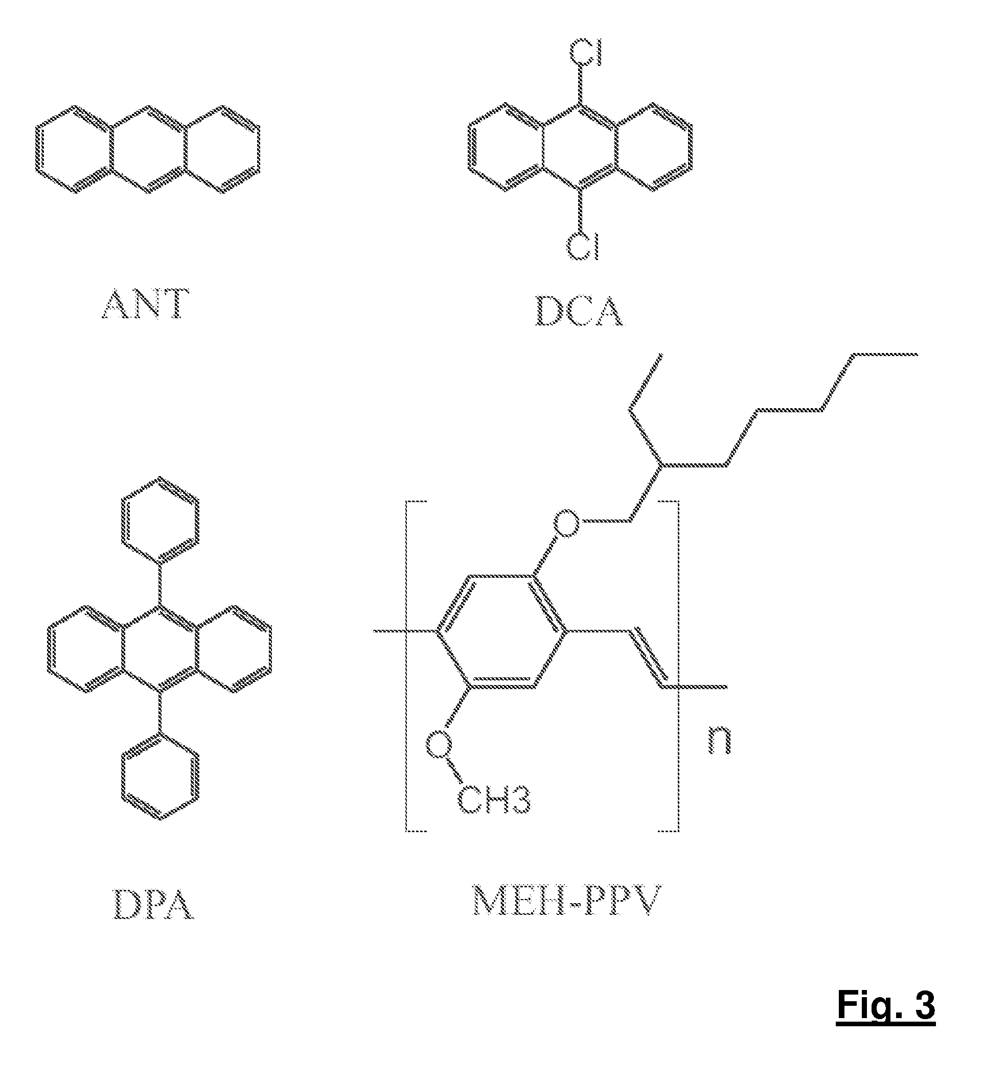
[0020] Preferably, the antenna consists of an ordered or aggregated assembly of molecules of a suitable material. An example is anthracene or an anthracene derivative. The aggregation generally improves the efficiency of the cell by enabling collective processes to redistribute the excitation energy most rapidly from the antenna to the active layer. Because the transfer of excitation from the antenna layer to the active layer proceeds by RET, no photons are generated in this step.
[0021] The light-harvesting molecules that comprise the antenna are not dispersed throughout the active layer, thereby avoiding interference with charge separation and carrier mobility in the active layer. This antenna may play secondary roles in assisting electron or hole transport as well as shielding the active layers from harmful UV radiation, thereby limiting photo-degradation.
[0023] Advantages of the present invention include: (a) improved energy conversion efficiency as measured using the AM1.5 incident solar spectrum; (b) improved efficiency of solar cells under low incident light conditions, for example in shaded, covered, or indoors environments; (c) improved efficiency for incident spectra different from AM1.5, for example northern latitudes on Earth, various types of indoor lighting, underwater, etc.; and (d) reduced photo-degradation of the active layers by reducing the UV exposure of the active layer.

Problems solved by technology

Currently the major disadvantages of organic solar cells relate to their low conversion efficiency, durability of organic materials when photo-excited continuously for long periods of time, the efficiency of photo-induced charge separation as well as electron and hole mobilities, and the fact that many of the active layers currently under investigation do not absorb the full range of light as is made available by the solar spectrum.
Replicating the complex pigment / protein interactions in photosynthetic proteins for use in man-made solar light harvesting devices is in general very complicated.
However, fundamental understanding of the physics that underlies the various processes and limits efficiencies in such devices is poor, hindering advancement.
However, this configuration is relatively inefficient for antenna layers of more than 10 nm thickness because it relies on an incoherent hopping mechanism.
However, this down-conversion mechanism has generally low energy transfer efficiency and consequently has limited applicability to, for example, the Si PV cells described therein.

Method used


Image

  • Light-harvesting antennae for organic solar cells
  • Light-harvesting antennae for organic solar cells
  • Light-harvesting antennae for organic solar cells

Examples


example 1

[0053] The light-harvesting efficiency of the present invention was demonstrated using systems consisting only of a clear quartz substrate, a bottom layer of MEH-PPV polymer, and a top antenna layer. These layers are prepared by sequentially spin coating MEH-PPV from chlorobenzene (˜250 nm) followed by spin-coating the antenna layer from acetonitrile solvent (˜150 nm). The film thicknesses and morphologies were determined by an ellipsometer and the surfaces were found to be somewhat rough, especially that of the antenna layer, where the anthracene and derivatives do not form a thin film, but rather recrystallize on the MEH-PPV. FIG. 4 illustrates the setup, with the organics spun on top of each other onto the quartz substrate. The order of the layers from bottom to top is quartz, ITO, PEDOT.PSS (a commonly used hole transport layer), antenna, blend of MEHPPV / C60 and aluminium electrode. The external circuit runs from the ITO anode to the aluminium cathode.

[0054] The spectral charac...

example 2

[0061] Organic solar cell devices were fabricated and tested as follows. All inch-squared ITO-coated glass cells were thoroughly cleaned by successive 5 minute sonications in detergent, deionized water, methanol, acetone, and isopropanol and were wiped and dried. Masks were applied to the cells using electrical tape about 2.5 mm into the entire perimeter of the cell. PEDOT.PSS was spin-coated on top of the ITO layer at a rate of 3000 rpm for 40 seconds, then 4000 rpm for the last 15 seconds, and left to cure at 150° C. in vacuo for 90 minutes. A second mask was then applied another 2.5 mm into the cell. A 0.6 wt. % 1:1 MEH-PPV(MW=900,000):C60 derivative solution in 1,2,4-trichlorobenzene was prepared in an N2 environment, after the solvent was purged with N2 prior to addition to the solids. A saturated anthracene solution using methanol was also made, the methanol also purged with N2 before addition to anthracene in an inert environment. Both solutions were kept in an N2 environment...


PUM

PropertyMeasurementUnit
Thicknessaaaaaaaaaa
Thicknessaaaaaaaaaa
Thicknessaaaaaaaaaa

Abstract

An antenna layer is provided separate from an active layer in a solar cell device based on organic materials, enabling improved energy conversion in the solar cell devices by increasing the efficiency and spectral cross-section for the capture of incident light. The antenna layer may be anthracene or an anthracene derivative, for example. The antenna layer is operable to harvest light and transfer captured excitation energy to the active layer of the solar cell device using an energy transfer mechanism, wherein the charge separation and / or the formation of free carriers takes place. The antenna layer also limits the ultraviolet exposure of the active layer thus extending the operating life of the solar cell. The active layer and the antenna layer of a solar cell device may be independently optimized such that there is an increased spectral range and / or cross-section of light absorption and thus a higher photovoltaic efficiency.

Description

PRIORITY [0001] This application claims the benefit of U.S. Provisional Patent Application No. 60 / 810,638, filed on 5 Jun. 2006.FIELD OF THE INVENTION [0002] The present invention relates to photovoltaic cells. The present invention more particularly relates to antennae for organic photovoltaic cells. BACKGROUND OF THE INVENTION [0003] Interest in polymer-based organic photovoltaic cells has increased over the past few years, as developments in technology, device engineering and the choice and range of materials used has improved solar energy conversion efficiencies above a 3% yield. Recent fundamental advances include polymer blends for improving charge separation, semiconductor nanocrystal-doped conjugated polymers, and fullerene-doped materials. Generally speaking, the advantages of organic solar cells lie in their ease of fabrication and subsequent low production costs, as well as the potential to exploit a vast array of possible chemical structures and functionalities of organi...

Claims


Application Information

Patent Timeline
IPC IPC(8): H01L31/04
CPCB82Y10/00H01L51/0037H01L51/0038Y02E10/549H01L51/0052H01L51/4253H01L2251/308H01L51/0046H10K85/1135H10K85/114H10K85/211H10K85/615H10K30/30H10K2102/103H10K30/50
Inventor SCHOLES, GREGORY DENTONDYKSTRA, TIENEKE EMILYYANG, XIUJUAN
Owner SCHOLES GREGORY DENTON
Learn More