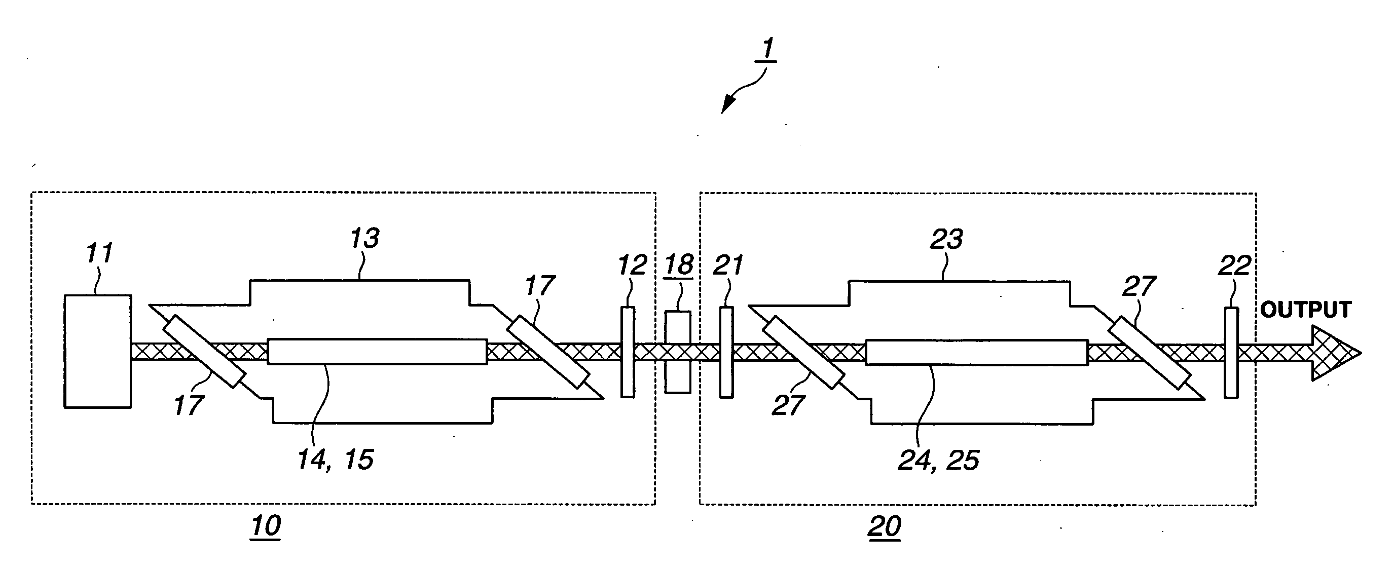
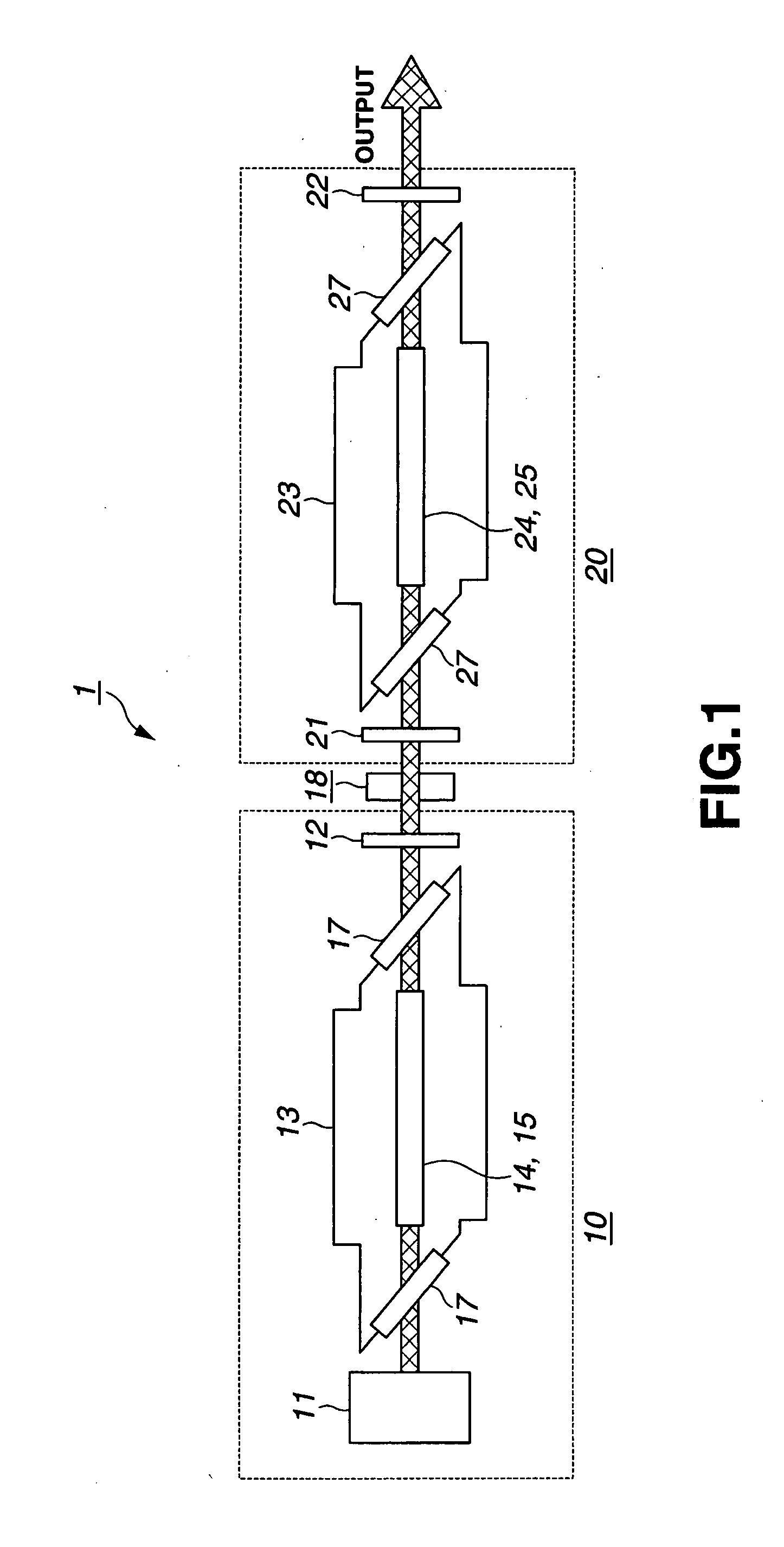
Excimer laser device
a laser device and high-output technology, applied in laser details, optical resonator shape and construction, active medium materials, etc., can solve the problems of deterioration of the window, affecting the life of the window, and increasing the output energy per pulse, etc., to achieve the effect of suppressing the deterioration of optical elements
- Summary
- Abstract
- Description
- Claims
- Application Information
AI Technical Summary
Benefits of technology
Problems solved by technology
Method used
Image
Examples
first embodiment
[0120]FIG. 4A is a conceptual diagram for explaining configuration of a conventional excimer laser device. FIG. 4B is a conceptual diagram for explaining configuration of a first embodiment of the present invention. Although common reference numerals with those of the amplification stage laser 20 in FIG. 1 are used in FIGS. 4A and 4B for convenience of explanation, the use of the common reference numerals simply means that those components are equivalent in function. The components bearing these reference numerals are not limited to the amplification stage laser 20 but may be applied to a single-chamber excimer laser device as well.
[0121]In the conventional excimer laser device as shown in FIG. 4A, the resonator optical axis 30 is parallel to the axes in the longitudinal direction of the discharge electrodes 24 and 25 provided in the laser chamber. Therefore, a gain region width W0 in the vertical direction in the paper sheet as viewed from the side of the resonator optical axis 30 ...
second embodiment
[0145]The description of the first embodiment has not specifically mentioned the resonator forming the resonator optical axis 30.
[0146]A second embodiment of the present invention assumes the amplification stage laser 20 of the two-stage laser system 1 shown in FIG. 3.
[0147]In the second embodiment, the axis in the longitudinal direction of discharge electrodes is tilted with respect to a resonator optical axis formed by arranging a rear-side mirror 21 and an output-side mirror 22 parallel to each other.
[0148]FIG. 12A is a diagram showing configuration of a conventional amplification stage laser 20. FIG. 12B is a diagram showing configuration of an amplification stage laser 20 according to the second embodiment. FIG. 12C shows a modification of the second embodiment.
[0149]In FIGS. 12A, 12B and 12C, the rear-side mirror 21 and the output-side mirror 22 are arranged in the amplification stage laser 20 parallel to each other, forming the resonator optical axis 30.
[0150]As shown in FIG....
third embodiment
[0165]A third embodiment of the present invention is applicable to a MOPO system using seed light.
Basic Principle and Simulation of Third Embodiment
[0166]A basic principle and simulation results of the third embodiment will be described.
[0167]FIG. 14 is a conceptual diagram for explaining how a laser beam is shifted at every reflection in the resonator according to the third embodiment.
[0168]A rear-side mirror 21 and an output-side mirror 22 are arranged in an amplification stage laser 20 parallel to each other, forming a resonator optical axis 30. A discharge electrode axis 32 is parallel to the resonator optical axis 30.
[0169]In the configuration described above, seed light is injected at a tilt angle θ with respect to the resonator optical axis 30 and reaches the output-side mirror 22 (this pass is referred as the “first pass”). When a distance between the rear-side mirror 21 and the output-side mirror 22 is denoted by M, the injected seed light will be shifted to the upper side ...
PUM
 Abstract
Description
Claims
Application Information
 - R&D
- Intellectual Property
- Life Sciences
- Materials
- Tech Scout
- Unparalleled Data Quality
- Higher Quality Content
- 60% Fewer Hallucinations
Browse by: Latest US Patents, China's latest patents, Technical Efficacy Thesaurus, Application Domain, Technology Topic, Popular Technical Reports.
© 2025 PatSnap. All rights reserved.Legal|Privacy policy|Modern Slavery Act Transparency Statement|Sitemap|About US| Contact US: help@patsnap.com


