
PTFE membranes and gaskets made therefrom

Inactive Publication Date: 2008-02-07
WL GORE & ASSOC INC
View PDF10 Cites 0 Cited by
  • Summary
  • Abstract
  • Description
  • Claims
  • Application Information

AI Technical Summary

Benefits of technology

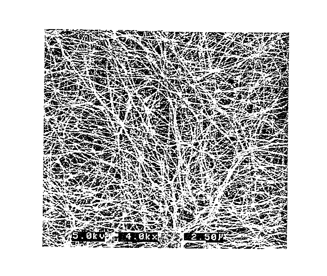
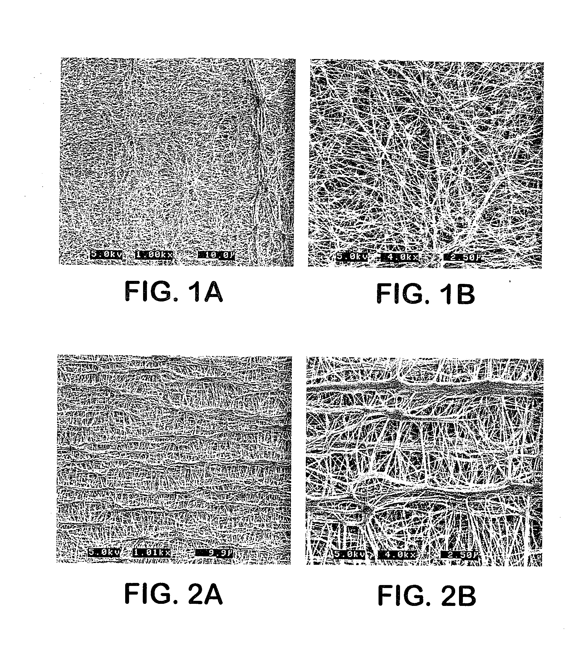
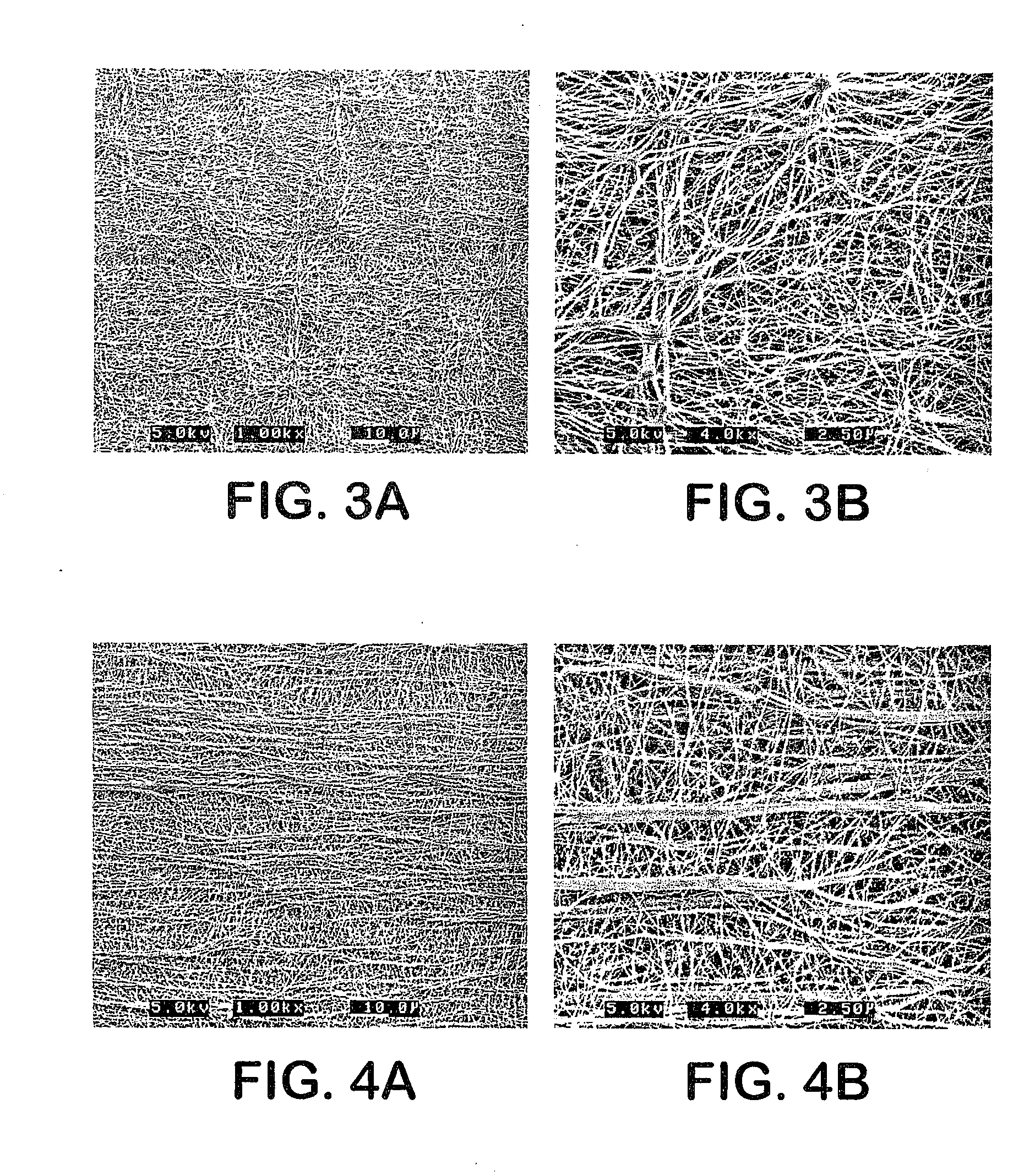
[0018] Expanded PTFE membranes of the present invention exhibiting such combinations of improved mechanical properties are prepared by ram extruding a lubricated PTFE powder to form a tape, then calendering, drying, stretching in the machine, or longitudinal, direction at temperatures at or above 325° C., then stretching perpendicular to the machine direction (i.e., the transverse direction) again at temperatures at or above 325° C. while constraining the tape from shrinking in the longitudinal direction, then subjecting the stretched tape to a 380° C. heat zone while constrained. A unique feature of the present invention is that by varying the degree of calendering of the tape, and by varying the stretch temperatures, stretch rates and stretch ratios for both directions, membranes which are surprisingly strong and which have very balanced strengths can be produced. In addition, higher crystallinity and lower orientation indices can be achieved. Suitable processing variations for achieving membranes with these enhanced properties are contained in the Examples herein.
[0019] It was discovered that the improved PTFE membranes of this invention can be incorporated into gasket materials and gaskets exhibiting improved mechanical properties such as high bolt load retention, low creep, high tensile strength, low stress to seal and high crystallinity index. Moreover, it was discovered that PTFE gaskets exhibiting the highest bolt load retention and lowest creep characteristics ever produced could be constructed using these improved PTFE membranes. As used herein for convenience, the term “gasket” is intended to refer to materials in sheet, tape or finished (i.e., cut or shaped, such as annular, etc.) gasket form.

Problems solved by technology

Unfortunately, non-expanded, non-porous PTFE gaskets are generally not conformable enough to effectively seal this type of equipment.
In the case of glass-lined steel flanges, although there is a relatively smooth finish, there is often a large amount of unevenness or lack of flatness associated with the flanges.
Thus, a non-expanded, non-porous PTFE gasket is not conformable enough to seal many of these applications.
Unfortunately, in many of these applications it is not possible to apply sufficient force to the flanges to create enough gasket stress to fully densify the expanded PTFE gasket to create an effective seal.
For example, glass-lined steel piping flanges, glass flanges, or FRP piping flanges may deform, fracture, or break upon the application of a high amount of stress.
Thus, in these applications, an expanded PTFE gasket may not be completely densified to reach a non-porous state, and therefore does not become leak proof, because the maximum stress that can be applied to the flanges without breaking them is not sufficient to so densify the gasket.
While expanded PTFE materials exhibit much better performance than non-expanded, non-porous PTFE in gasket applications, it still exhibits some propensity to creep, or flow, under load.
Typically, the higher the bolt load on a gasket the lower the leakage will be from that gasketed assembly.
PTFE gaskets (i.e., greater than about 50% PTFE, by weight) are prone to creep and stress relaxation when subjected to a compressive load.

Method used


Image

  • PTFE membranes and gaskets made therefrom
  • PTFE membranes and gaskets made therefrom
  • PTFE membranes and gaskets made therefrom

Examples


examples

[0071] The present invention will now be described in conjunction with the following examples which are intended to illustrate the invention, not to limit it. In the examples, the following test methods were used.

Test Methods

DSC Measurement

[0072] Differential Scanning Calorimetry (DSC) was performed to determine the crystalline state of the material both before and after the transverse expansion process. The characterization before transverse expansion is performed to determine the level of heat conditioning that was applied through the machine direction expansion process. The equipment used to perform these measurements was a TA Differential Scanning Calorimeter (Model # 2920), calibrated using an appropriate standard, with an attached refrigerated cooling unit (TA RCS Model #991100.901).

[0073] Sample preparation was accomplished by first cutting (using a scalpel or razor blade) a sample weighing approximately 10 milligrams out of the center of the ePTFE membrane web. The bal...

example 1

[0117] An expanded PTFE membrane was produced by practicing the following steps in sequence: [0118] 1. Blending PTFE fine powder (PTFE 601A, DuPont, Wilmington, Del.) with a lubricant (Isopar K, Exxon, Houston, Tex.) in the proportion of 130 cc / lb [0119] 2. Compressing the lubricated powder into a cylindrical shape [0120] 3. Paste extruding at a reduction ratio of 135:1 [0121] 4. Calendering to a thickness of 0.018 inch [0122] 5. Drying the tape in a convection oven set to 210° C. [0123] 6. Longitudinally stretching the tape between two banks of rollers separated by a 325° C. heat zone [0124] 7. Transversely stretching the longitudinally stretched tape in a 335° C. heat zone, while constraining the tape from shrinking in the longitudinal direction [0125] 8. Subjecting the stretched tape to a 380° C. heat zone while constrained.

[0126] The stretch rates for the longitudinal and transverse directions were 39.7% / sec and 56.2% / sec, respectively. The stretch ratios for the longitudinal a...

example 2

[0129] Another membrane was made in accordance with the process described in Example 1 with the following exceptions. The stretch ratios for the longitudinal and transverse directions were 4.1:1 and 7.6:1, respectively.

[0130] The calendered tape process conditions were the same, yielding approximately the same longitudinal and transverse strengths. The final membrane had matrix tensile strengths in the longitudinal and transverse directions of about 186 MPa and 175 MPa, respectively. The membrane density was 0.38 g / cc. The orientation index was 27.62° and the crystallinity index was 55.06%.


PUM

PropertyMeasurementUnit
Lengthaaaaaaaaaa
Fractionaaaaaaaaaa
Fractionaaaaaaaaaa

Abstract

Improved expanded PTFE materials and improved gasket materials made therefrom, the gaskets being capable of forming a seal with greater bolt load retention than is possible with existing PTFE gaskets. The expanded PTFE membranes of the invention can be tailored to exhibit a matrix tensile strength in at least one direction of at least 25,000 psi, a matrix tensile strength ratio in two orthogonal directions of between 0.025 and 4, an orientation index of 50° or less, and a density of 2.0 g / cc or less. The improved gaskets exhibit improved mechanical properties such as high bolt load retention, low creep, high tensile strength, low stress to seal and high crystallinity index.

Description

RELATED APPLICATIONS [0001] The present application is a divisional application of U.S. patent application Ser. No. 11 / 059,849, filed Feb. 16, 2005, which is a divisional application of U.S. patent application Ser. No. 10 / 382,668, filed Mar. 6, 2003, now abandoned.FIELD OF THE INVENTION [0002] The present invention relates to improved expanded PTFE materials and to improved gaskets made therefrom, the gaskets being capable of forming a seal with greater bolt load retention than is possible with existing PTFE gaskets. BACKGROUND OF THE INVENTION [0003] A wide variety of gaskets are known for use in sealing applications. Expanded polytetrafluoroethylene (PTFE) is widely used today as a gasket material. As disclosed in U.S. Pat. No. 3,953,566 to Gore, this material has numerous properties making it highly desirable as a gasket. These properties include being readily compressible and conformable, being chemically resistant, having relatively high strength, and being far less prone to cr...

Claims


Application Information

Patent Timeline
IPC IPC(8): F16J15/02E04B1/682F16J15/10B29C48/475F16L23/22
CPCB29C47/0021B29C47/54B29K2027/18B29L2031/265Y10T428/269F16J15/104F16J15/3284F16L23/22Y10T428/215F16J15/102B32B2307/548B32B7/12B32B27/08B32B27/205B32B27/322B32B3/26B32B2307/50B32B2307/54B32B2307/546B32B2307/552B32B2307/714B32B2307/72B32B2307/7242B32B2307/732B32B2581/00B29C48/08B29C48/475Y10T428/249978
Inventor BOWEN, CHRISTOPHERDOVE, KEVIN EDWARDJONES, CARLMINOR, RAYMOND B.
Owner WL GORE & ASSOC INC
Learn More