Joint arthroplasty devices formed in situ

Inactive Publication Date: 2007-10-25
CONFORMIS
View PDF99 Cites 325 Cited by
  • Summary
  • Abstract
  • Description
  • Claims
  • Application Information

AI Technical Summary

Benefits of technology

[0013] The present invention provides novel devices and methods for replacing or resurfacing a portion (e.g., diseased area and / or area slightly larger than the diseased area) of a joint or all of a joint (e.g., cartilage and / or bone, one or two articular surfaces) with an implant material, where the implant can achieve a near anatomic fit with the surrounding structures and tissues. In cases where the devices and / or methods include an element associated with the underlying articular bone, the invention also provides that the bone-associated element can achieve a near anatomic alignment with the subchondral bone. The invention also provides for the preparation of an implantation site with a debridement, shaping of the articular surface or subchondral bone, a single cut, or a few relatively small cuts.
[0015] In any of the methods described herein, one or more components of the articular replacement material (e.g., the cartilage replacement material) can be non-pliable, non-liquid, solid or hard. The dimensions of the replacement material can be selected following intraoperative measurements. Measurements can also be made using imaging techniques such as ultrasound, MRI, CT scan, x-ray imaging obtained with x-ray dye and fluoroscopic imaging. A mechanical probe (with or without imaging capabilities) can also be used to select dimensions, for example an ultrasound probe, a laser, an optical probe and a deformable material or device. A surgical navigation system can be used to improve the accuracy of intraoperative placement. Other imaging techniques such as CT or MRI, optionally with near real-time imaging capability can be employed.

Problems solved by technology

Adult cartilage has a limited ability of repair; thus, damage to cartilage produced by disease, such as rheumatoid and / or osteoarthritis, or trauma can lead to serious physical deformity and debilitation.
However, clinical outcomes with biologic replacement materials such as allograft and autograft systems and tissue scaffolds have been uncertain since most of these materials cannot achieve a morphologic arrangement or structure similar to or identical to that of normal, disease-free human tissue it is intended to replace.
Moreover, the mechanical durability of these biologic replacement materials remains uncertain.
Implantation of prosthetic devices is usually associated with loss of underlying tissue and bone without recovery of the full function allowed by the original cartilage and, with some devices, serious long-term complications associated with the loss of significant amount of tissue and bone can include infection, osteolysis and also loosening of the implant.
Further, joint arthroplasties are highly invasive and require surgical resection of the entire or the majority of the articular surface of one or more bones.
The reaming results in a loss of the patient's bone stock.
Implantation of these prosthetic devices is usually associated with loss of underlying tissue and bone without recovery of the full function allowed by the original cartilage and, with some devices, serious long-term complications associated with the loss of significant amounts of tissue and bone can cause loosening of the implant.
One such complication is osteolysis.
Since the patient's bone stock is limited, the number of possible replacement surgeries is also limited for joint arthroplasty.
As can be appreciated, joint arthroplasties are highly invasive and require surgical resection of the entire, or a majority of the, articular surface of one or more bones involved in the repair.
Reaming results in a loss of the patient's bone stock and over time subsequent osteolysis will frequently lead to loosening of the prosthesis.
Further, the area where the implant and the bone mate degrades over time requiring the prosthesis to eventually be replaced.
Since the patient's bone stock is limited, the number of possible replacement surgeries is also limited for joint arthroplasty.
In short, over the course of 10 to 15 years, and in some cases even shorter time periods, the patient can run out of therapeutic options ultimately resulting in a painful, non-functional joint.
Currently available devices do not always provide ideal alignment with the articular surfaces and the resultant joint congruity.
Poor alignment and poor joint congruity can, for example, lead to instability of the joint.
In the knee joint, instability typically manifests as a lateral instability of the joint.

Method used


Image

  • Joint arthroplasty devices formed in situ
  • Joint arthroplasty devices formed in situ
  • Joint arthroplasty devices formed in situ

Examples


Embodiment Construction

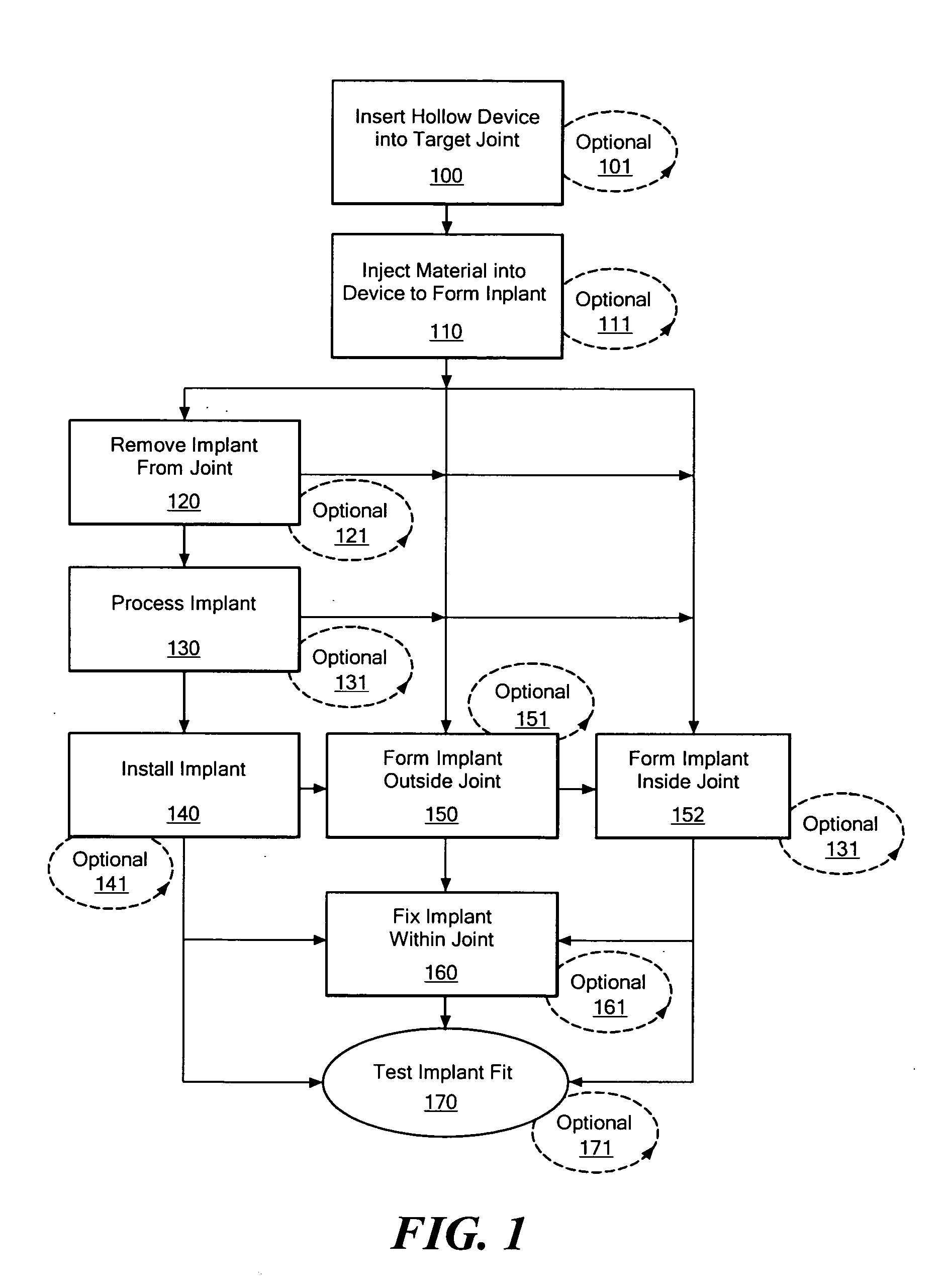
[0032] The following description is presented to enable any person skilled in the art to make and use the invention. Various modifications to the embodiments described will be readily apparent to those skilled in the art, and the generic principles defined herein can be applied to other embodiments and applications without departing from the spirit and scope of the present invention as defined by the appended claims. Thus, the present invention is not intended to be limited to the embodiments shown, but is to be accorded the widest scope consistent with the principles and features disclosed herein. To the extent necessary to achieve a complete understanding of the invention disclosed, the specification and drawings of all issued patents, patent publications, and patent applications cited in this application are incorporated herein by reference.

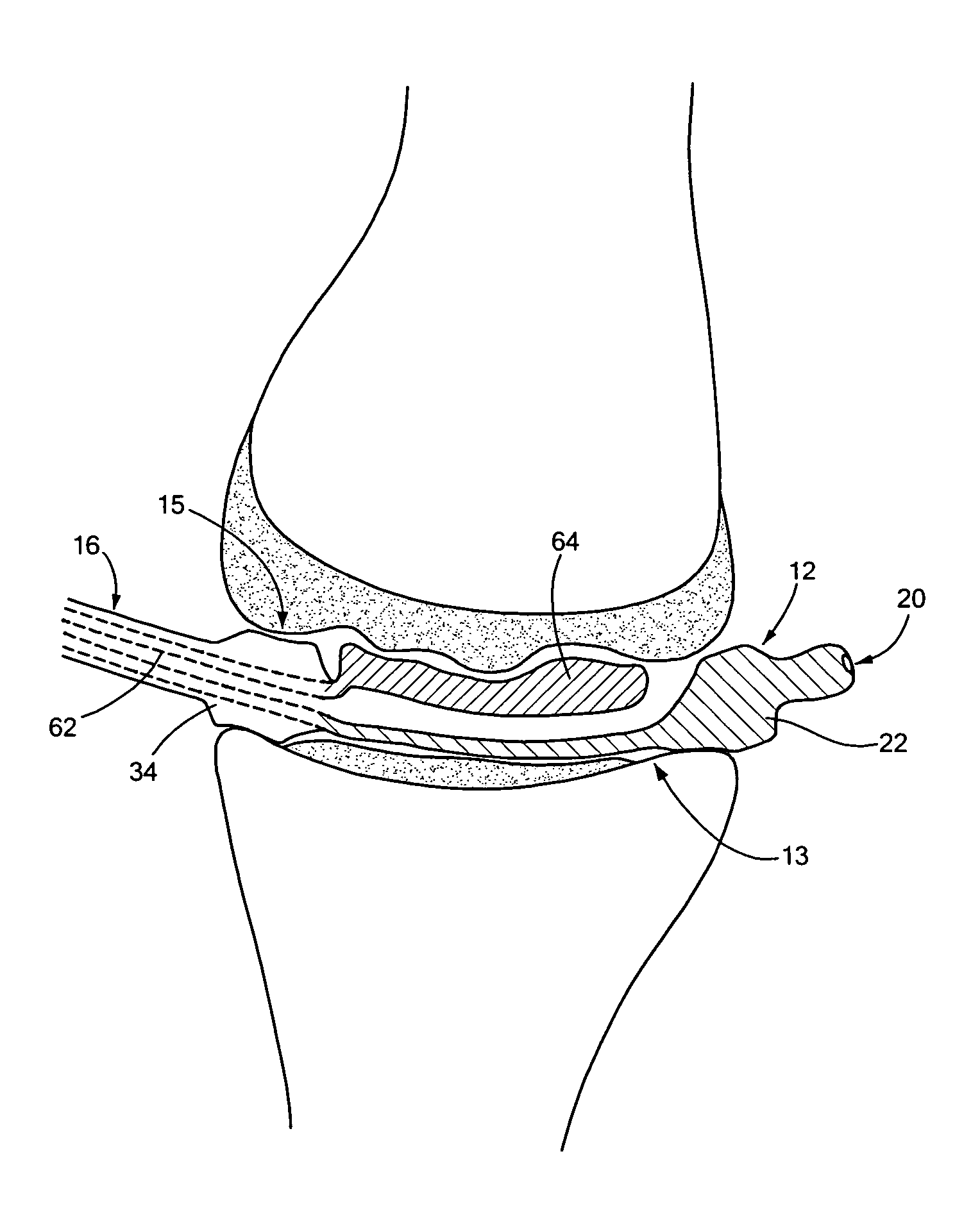
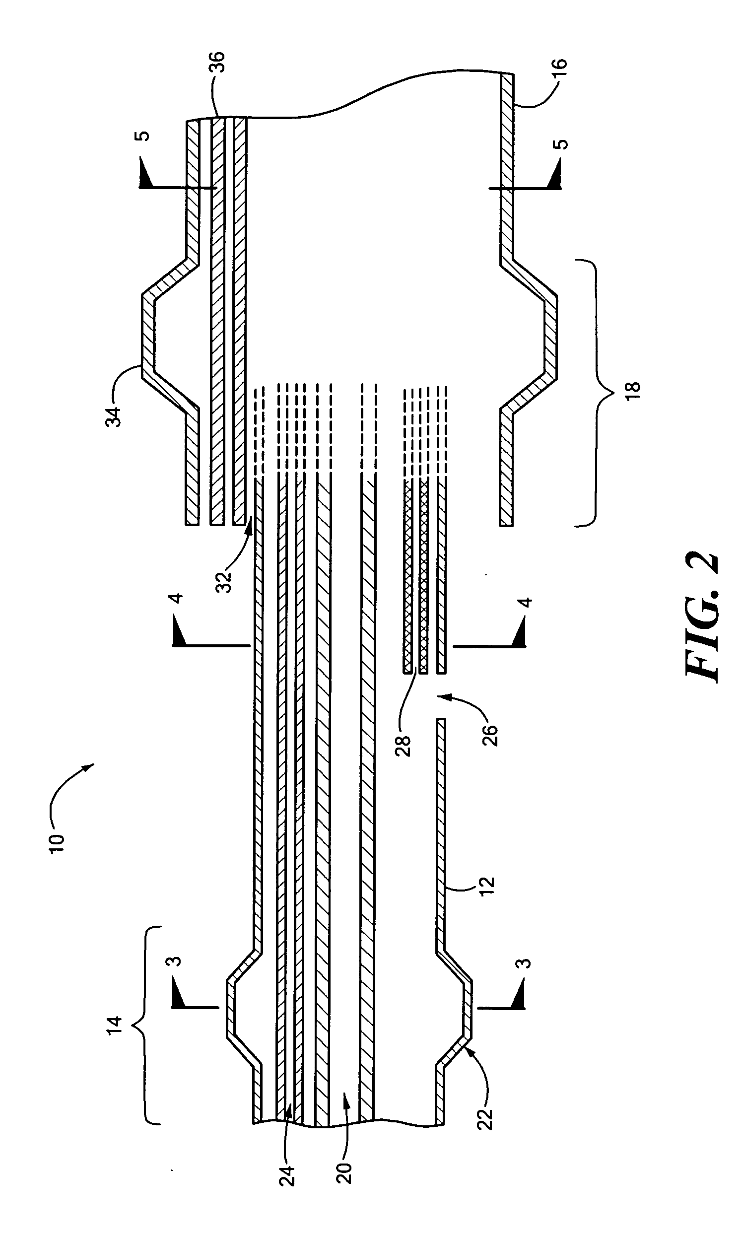
[0033] The present invention provides methods and compositions for repairing joints, particularly for repairing articular cartilage and for ...


PUM

PropertyMeasurementUnit
Lengthaaaaaaaaaa
Thicknessaaaaaaaaaa
Stiffnessaaaaaaaaaa

Abstract

Disclosed herein are methods and devices for repairing articular surfaces. The articular surface repairs are customizable or highly selectable by patient and geared toward providing optimal fit and function.

Description

CROSS-REFERENCE TO RELATED APPLICATIONS [0001] This is a continuation of U.S. Ser. No. 60 / 630516 entitled “Joint Arthroplasty Devices Formed in Situ” filed Nov. 23, 2004 and a continuation-in-part of U.S. Ser. No. 10 / 724,010 entitled “METHODS AND COMPOSITIONS FOR ARTICULAR REPAIR” filed Nov. 25, 2003 which is a continuation-in-part of U.S. Ser. No. 10 / 305,652 entitled “METHODS AND COMPOSITIONS FOR ARTICULAR REPAIR,” filed Nov. 27, 2002, which is a continuation-in-part of U.S. Ser. No. 10 / 160,667, filed May 28, 2002, which in turn claims the benefit of U.S. Ser. No. 60 / 293,488 entitled “METHODS TO IMPROVE CARTILAGE REPAIR SYSTEMS”, filed May 25, 2001, U.S. Ser. No. 60 / 363,527, entitled “NOVEL DEVICES FOR CARTILAGE REPAIR,” filed Mar. 12, 2002 and U.S. Ser. Nos. 60 / 380,695 and 60 / 380,692, entitled “METHODS AND COMPOSITIONS FOR CARTILAGE REPAIR,” and “METHODS FOR JOINT REPAIR,” filed May 14, 2002, all of which applications are hereby incorporated by reference in its entirety.FIELD OF T...

Claims


Application Information

Patent Timeline
IPC IPC(8): A61F2/44A61B17/15A61B17/16A61B17/17A61B17/88A61B19/00A61F2/00A61F2/08A61F2/30A61F2/36A61F2/38A61F2/42A61F2/46A61F2/50G06T7/00G06T17/00
CPCA61B5/1075A61B5/1076A61B5/1077A61B5/4504A61B5/4514A61B5/4528A61B17/15A61B17/155A61B17/157A61B17/158A61B17/1662A61B17/1666A61B17/1668A61B17/7098A61B17/8805A61B19/50A61B19/5244A61B2017/568A61B2019/461A61B2019/502A61B2019/505A61B2019/508A61B2019/566A61F2/30756A61F2/30767A61F2/30942A61F2/36A61F2/3859A61F2/4202A61F2/4261A61F2/4405A61F2/441A61F2/442A61F2/46A61F2/4603A61F2/4657A61F2002/30581A61F2002/30583A61F2002/30604A61F2002/30612A61F2002/30733A61F2002/30878A61F2002/30884A61F2002/30894A61F2002/30909A61F2002/30948A61F2002/3095A61F2002/30957A61F2002/30962A61F2210/0085A61F2310/00011A61F2310/00017A61F2310/00023A61F2310/00029A61F2310/00047A61F2310/00065A61F2310/00071A61F2310/00077A61F2310/00083A61F2310/00107A61F2310/00113A61F2310/00119A61F2310/00131A61F2310/00143A61F2310/00149A61F2310/00155A61B2034/102A61B2034/256A61B34/20A61B2090/061A61B34/10A61B2034/105A61B2034/108B33Y80/00
Inventor LANG, PHILIPP
Owner CONFORMIS
Why Eureka
Try Eureka