
Composite fuels for hydrogen generation

a technology of composite fuels and hydrogen, which is applied in the direction of fuels, electrochemical generators, other chemical processes, etc., can solve the problems of reducing the realization of hydrogen economy, methanol fuel also decomposing into carbon monoxide, reaction taking more thermal energy, etc., and achieves high gravimetric and volumetric energy density, high hydrogen content, and reduced complexity and cost.

Active Publication Date: 2007-08-23
EION ENERGY CORP
View PDF8 Cites 11 Cited by
  • Summary
  • Abstract
  • Description
  • Claims
  • Application Information

AI Technical Summary

Benefits of technology

[0017] One of the advantages of these composite fuels is their high hydrogen content, which leads to high gravimetric and volumetric energy density for fuel cell power systems.
[0018] Another advantage of these composite fuels is that they generate pure hydrogen in a single step. No greenhouse gases or other gas phase impurities are generated, so the hydrogen product need not be further cleaned. This reduces the complexity, cost, and size of a power system.
[0019] The composite fuels require minimal energy to extract hydrogen. Thus, a power system using this hydrogen generation mechanism has higher energy efficiency. Hydrogen can be generated from these composite fuels at temperature well below 200° C. The low operating temperature is beneficial to the integration of power products. The fuels are stable in a wide range climatic conditions, are safe for storage, and have a long shelf life. All the residues of hydrogen generation with these fuels are environmentally safe. The present invention provides primary composite fuels that enable efficient generation of hydrogen on demand and on-spot. The fuel ingredients are optimized to ensure high energy density, economy, and stability in wide climatic and storage conditions.

Problems solved by technology

Issues from hydrogen production, storage and transportation have slowed down the realization of a hydrogen economy.
Furthermore, at such a high temperature methanol fuel also decomposes into carbon monoxide:
This reaction takes more thermal energy than reforming reaction (1) and also releases poisonous carbon monoxide.
The presence of carbon dioxide and carbon monoxide in the product gas stream will greatly reduce the value of this process for low temperature fuel cells, such as alkaline fuel cells (AFC) and polymer electrolyte membrane fuel cells (PEMFC).
These treatments further reduce energy efficiency, add cost, and make the system very bulky and complex, which greatly limits its application.
In addition of these problems, using methanol as the primary fuel also leads to the risk of exposure of methanol vapor at high temperature, creating safety concerns, especially for portable power applications.
Because of the slow kinetics of reforming these fuels, a large catalyst package is required, which limits application of the process to stationary fuel cell power.
Because the process temperature is much higher than the boiling point of water, a high pressure vessel is needed to conduct liquid phase reforming, greatly reducing the gravimetric energy density of the system and creating safety concerns for portable power applications.
However, this process generates a lot of waste heat and drives the temperature of the fuel processor up to 200° C., which causes rapid loss of water vapor and leaves a solid by-product (sodium borate) in the catalyst bed.
The extra alkali materials reduce the fuel energy density, increase fuel cost, and create environmental risk upon disposal of the fuel cartridge.
Another problem with this fuel is its freezing point.
The fuel storage container or cartridge can only be used at temperatures above 0° C. or even above 18° C. This problem limits its application to areas with warm climates.
The prior art is focused on methods to process a single primary fuel to generate hydrogen, but fails to make hydrogen generation simple and more energy efficient.

Method used


Image

  • Composite fuels for hydrogen generation
  • Composite fuels for hydrogen generation
  • Composite fuels for hydrogen generation

Examples


example 1

[0055] 2 moles of sodium hydroxide were added to purified water to make a 45 wt % NaOH solution. 1 mole of ethylene glycol was then added to the solution to make a composite fuel for hydrogen generation. 0.5 mole of sodium borohydride was slowly added to the alkaline solution. The obtained composite fuel is a clear solution.

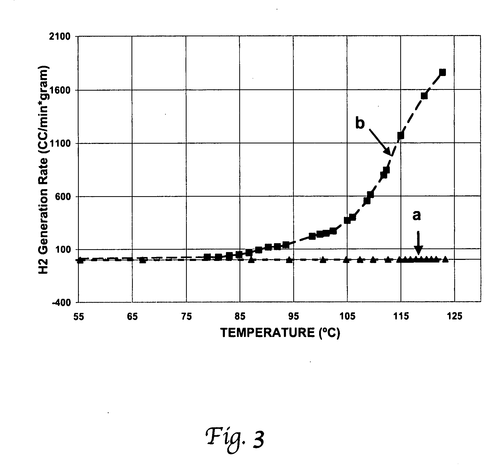
[0056] This solution is very stable over a wide range of climatic conditions. The fuel cartridge withstood the temperature of a freezer without freezing. The thermal stability of the composite fuel at high temperature was tested in a Teflon container with a heating element. No gas evolving from the solution was observed or measured. The test result of stability of the fuel at high temperature is shown in FIG. 3, line a. This shows that the fuel is stable up to 125° C.

[0057] With the same setup but in the presence of carbon supported Pt—Ru catalysts, hydrogen generation is observed and measured. The hydrogen generation rate using this fuel was measured at differ...

example 2

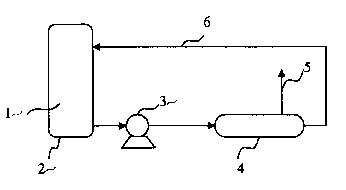
[0060] By pumping the same composite fuel as in Example 1 into a preheated adiabatic catalytic processor at 150° C. as illustrated in FIG. 1, the hydrogen generation starts once the fuel contacts the catalysts, and the temperature of the processor can be maintained constant during hydrogen generation even with no extra heat input.

example 3

[0061] 80 grams of sodium borohydride powder, 80 grams of sodium hydroxide and 5 grams carbon supported Ni, Co and Fe catalyst are well mixed together under a nitrogen atmosphere. Then 62 grams of ethylene glycol is slowly added to the mixture prepared above, and a paste form of composite fuel is formed. The paste is then laminated between 7-mil high porous polyethylene sheets and becomes a pellet. Multiple laminated fuel pellets are packed together into a plastic container. When water is fed into the container, hydrogen is produced. The generation rate of hydrogen is controlled by the feed rate of water.


PUM

PropertyMeasurementUnit
temperatureaaaaaaaaaa
temperaturesaaaaaaaaaa

Abstract

Composite fuels for hydrogen generation include materials that endothermically release hydrogen, materials that exothermically release hydrogen, and additives to promote endothermic reaction and to inhibit exothermic reaction.

Description

RELATED APPLICATION [0001] This application claims the benefit of U.S. Provisional Patent Application Ser. No. 60 / 774,874 filed Feb. 18, 2006.BACKGROUND OF THE INVENTION [0002] 1. Field of Invention [0003] Composite fuels that can be converted to hydrogen include materials that endothermically release hydrogen, materials that exothermically release hydrogen, and additives to promote endothermic reaction and to inhibit exothermic reaction. [0004] 2. Description of the Related Art [0005] Hydrogen is considered a future fuel for the globe. It contains high energy, enables high energy conversion efficiency, and is environmentally benign. Hydrogen enabled fuel cell power could be widely used for transportation, stationary, and portable power applications. Through a fuel cell device, hydrogen fuel electrochemically combines with oxygen from air to generate power with heat, and leaves water as the only exhaust. But hydrogen must be extracted or made from hydrogen-containing materials, such...

Claims


Application Information

Patent Timeline
Patent Type & Authority Applications(United States)
IPC IPC(8): C09K3/00H01M8/06
CPCC01B3/02C01B3/065Y02E60/50H01M8/0612Y02E60/362C25B1/02Y02E60/36
Inventor ZHAO, QINGJUNLUO, YUYAN
Owner EION ENERGY CORP
Learn More