
Directly connected magnetron powered self starting plasma plume igniter

Inactive Publication Date: 2007-08-09
PESCHEL WILLIAM P
View PDF13 Cites 5 Cited by
  • Summary
  • Abstract
  • Description
  • Claims
  • Application Information

AI Technical Summary

Benefits of technology

[0009] The present invention is an igniter for igniting and maintaining flame in an aircraft gas turbine or a rocket engine. It involves generating a plasma of either oxidizer or fuel using microwave electromagnetic energy, and injecting the plasma as a plume into the combustion chamber of the engine. The microwave electromagnetic energy used to create and maintain the plasma plume is provided by a magnetron that is directly connected to a coaxial transmission line, rather than being coupled to it through a waveguide and associated antennas, as is done in the prior art. The direct connection of the magnetron to the coax transmission line avoids the necessity of providing a waveguide coupling, and hence saves space and weight, and improves electrical efficiency.
[0017] Either a fuel or an oxidizer plasma may be used in this configuration, but an oxygen plasma is preferred. An oxygen plasma is extremely reactive; it combines with fuel instantaneously and continuously in the pre-burner region to develop an extremely robust pilot flame that projects well into the combustion chamber. The pre-burner, being integrated with the igniter, promotes complete combustion in the pilot flame, and cannot be blown out because the continuously generated oxygen plasma functions as a stabilizing flameholder.
[0018] As used in an aircraft gas turbine engine (which includes turbojet and turbofan engines) the present invention, employing the second configuration, can provide a high energy plasma plume which extends well into the combustor (or augmentor) section of the engine to ignite the flowing fuel / air mixture existing in the engine. The igniter can be operated either in continuous or in intermittent modes, as desired, to achieve the desired results. Using simply air as the oxidizer feed gas, a plasma plume can be generated that can maintain combustion in the combustor or augmentor without the need of flameholders.

Problems solved by technology

It must be recognized, however, that these igniters do not and cannot sustain combustion, they only ignite the flowing fuel-air mixture for the duration of each plasma pulse.
The fuel / air mixture in a turbojet or rocket combustor region near the walls could be in a less than optimum condition for ignition due to cold surroundings and boundary layer mixing limitations.
On the other hand, cavity type plasma jet spark devices have significant disadvantages in aircraft jet engine applications.
Commonly available systems are limited to about 100 to 300 discharges per minute if minimally adequate energy is to be transferred.
This is a severe disadvantage during a landing approach or under bad weather flight conditions, when assurance of engine ignition is critical.
It is also a disadvantage when attempting to relight a flamed out engine at high altitudes.
Whichever spark discharge design is used, plug technology is extremely sensitive to excess quantities of fuel (rich mixtures) which can be developed in emergency or inclement weather relight situations.
These devices have not generally been thought suitable for use as engine igniters because they have not been self-starting, requiring some sort of triggering spark to initiate the plasma.

Method used


Image

  • Directly connected magnetron powered self starting plasma plume igniter
  • Directly connected magnetron powered self starting plasma plume igniter
  • Directly connected magnetron powered self starting plasma plume igniter

Examples


Embodiment Construction

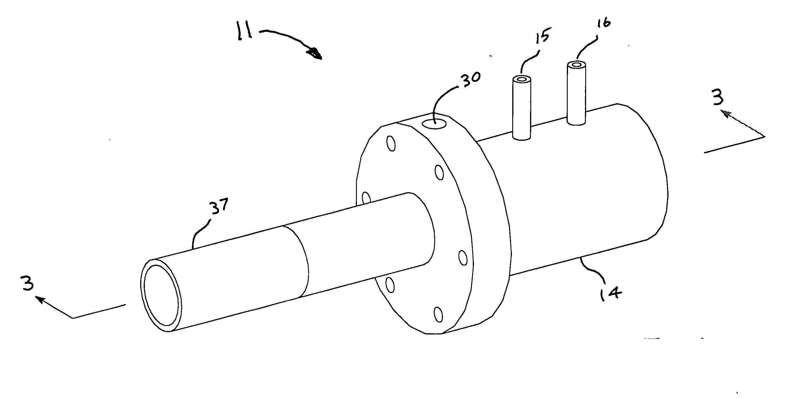
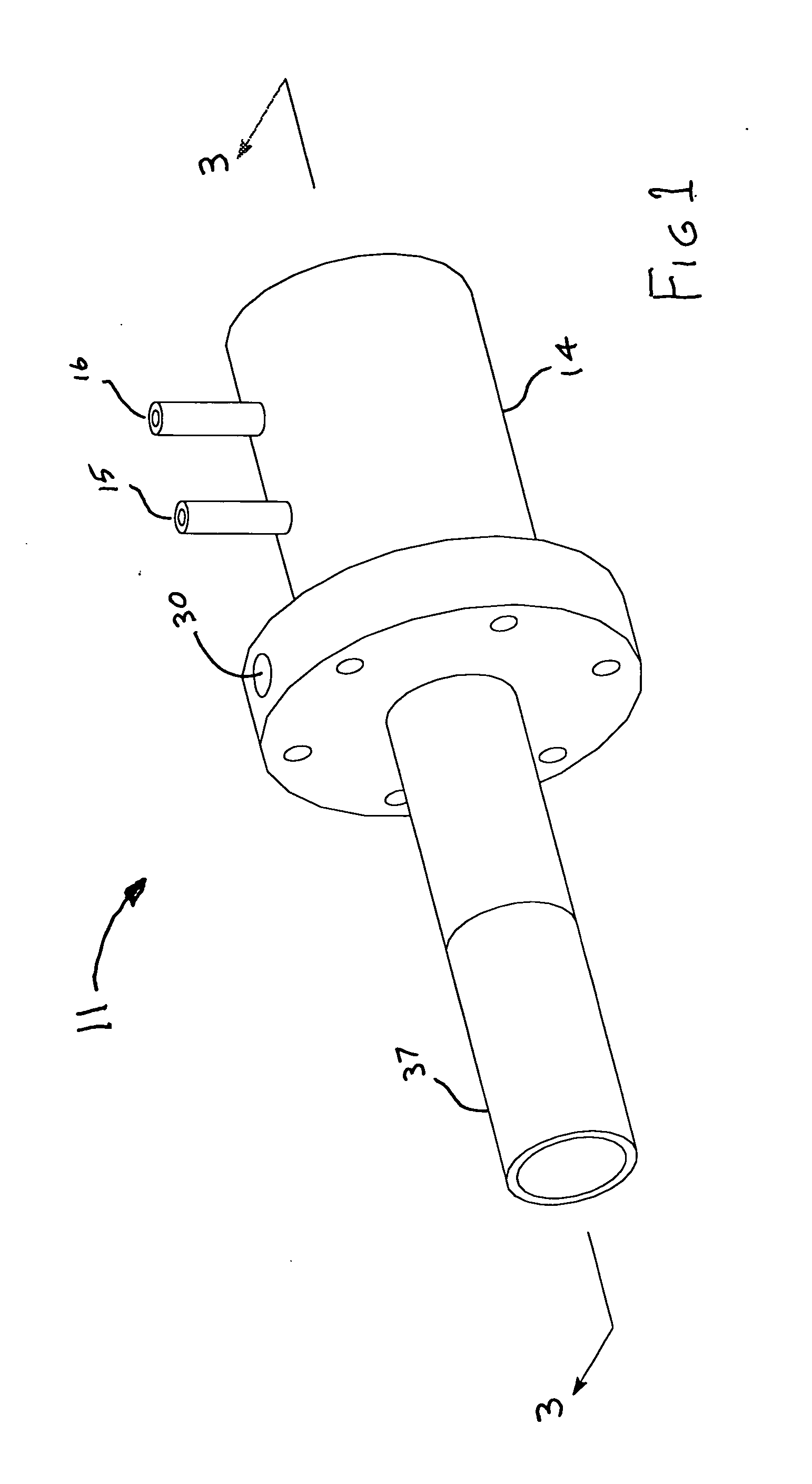
[0029]FIG. 1 depicts a trimetric view of a first embodiment 11 of the invention. The embodiment shown is a “straight through” configuration, as opposed to the right angle version depicted in FIG. 8.

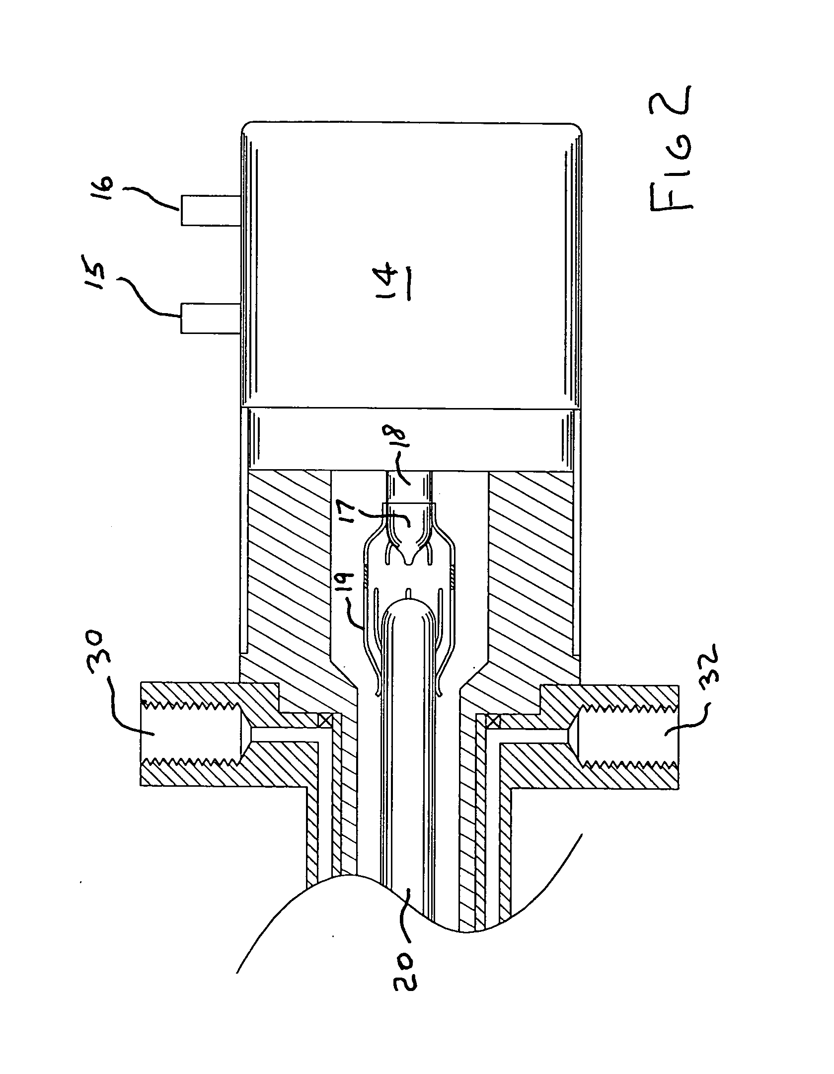
[0030]FIG. 2 shows a partially sectioned side view of the magnetron end of the igniter shown in FIG. 1. Magnetrons having a power output rating in the range between 600 watts and 2 kilowatts are preferred, but powers outside this range may be used, if desired. Rated power in the preferred range provides an adequately robust plasma for most uses, without dissipating excessive heat. More preferred yet is a magnetron having a power output rating of 1.3 kilowatts. A frequency of about 2.45 GHz, which is a commonly used frequency for magnetrons, has been found to function well.

[0031] Substantial heat is generated by magnetrons, and external cooling is generally required. The preferred form of cooling is by liquid flowing through cooling coils within the magnetron, but other forms of cooling ...


PUM

PropertyMeasurementUnit
Massaaaaaaaaaa
Pressureaaaaaaaaaa
Angleaaaaaaaaaa

Abstract

An igniter for use in aircraft gas turbine and rocket engines that derives its energy from a directly connected magnetron. The igniter is intended to be mounted exterior of the engine, and to protrude into the engine's combustion chamber. The magnetron energy is conductively connected to one end of a coaxial transmission line. The other end of the transmission line is at a region of high potential, and there is a small gap between the inner and outer transmission line conductors in that region. A gas comprised of either an oxidizer or fuel is flowed past the gap, and into the combustion chamber of the engine. The high potential causes a plasma to be formed in the gas, which plumes into the combustion chamber and ignites the propellants flowing therein. In another embodiment disclosed, instead of the plasma flowing directly into the combustion chamber after creation, it flows for a short distance in a pre-burner section of the igniter where fuel is added in the case of an oxidizer plasma, or oxidizer is added in the case of a fuel plasma. In either case, a flaming mixture is created which is then injected into the combustion chamber to ignite the propellants. Both straight through embodiments and embodiments having a right angle bend in the transmission line are disclosed.

Description

BACKGROUND OF THE INVENTION [0001] Turbojet, turbofan, and rocket engines of current design are generally started using spark discharge igniters that protrude into the engine's combustion chamber, or into a precombustion chamber and ignition flame tube, as in the Space Shuttle main rocket engine. A commonly used igniter type employs a high voltage source (several tens of kilovolts) which is repeatedly discharged across a gap in a manner similar to ordinary automobile spark plugs. One particular design of this type is called a cavity type plasma jet igniter. The spark plugs used with this type system have a small cavity integrated into the region where the electrodes are located. When fired, the arc discharge ejects or puffs-out a heated volume of gas through an orifice in the cavity into the fuel / air mixture, the heated volume including a plasma filament. [0002] Variations of this type of plug, in combination with surface discharge spark initiation features, have become widely used ...

Claims


Application Information

Patent Timeline
IPC IPC(8): H01J7/24H05B31/26
CPCF02C7/266F05D2260/85H05H1/46F02K9/95
Inventor PESCHEL, WILLIAM P.
Owner PESCHEL WILLIAM P
Learn More