
Probe cards employing probes having retaining portions for potting in a retention arrangement

Inactive Publication Date: 2007-06-14
MICRO PROBE
View PDF5 Cites 11 Cited by
  • Summary
  • Abstract
  • Description
  • Claims
  • Application Information

AI Technical Summary

Benefits of technology

[0008] In view of the above prior art limitations, it is an object of the invention to provide for a method and apparatus for electrical testing of devices under test (DUTs) that have densely spaced contact pads or bumps. The object is to ensure that the probes used in such apparatus are appropriately held and designed to ensure advantageous mechanical properties, including resilience, compliance and scrub motion.
[0009] It is another object of the invention to ensure that the apparatus is easy to assemble and disassemble despite the small pitch of the probes.
[0010] These and other objects and advantages of the invention will become apparent from the ensuing description.
[0011] The objects and advantages of the invention are secured by a method and an apparatus for electrical testing of a device under test (DUT). The apparatus has a plurality of probes, each of which has a connect end for applying a test signal, a retaining portion, at least one arm portion and a contacting tip for making an electrical contact with the DUT, and more specifically with a pad or bump of the DUT. The apparatus has a retention arrangement for holding each of the probes by its retaining portion. The retention arrangement has a top plate with top openings for the probes, a bottom plate with bottom openings for the probes and a potting enclosure

Problems solved by technology

Unfortunately, merely providing a geometry or method of holding probes that can address a dense array of pads is not sufficient.
Although the prior art solutions individually address some of the problems, there is no apparatus or method that combines the requisite characteristics in a single probe card or testing apparatus.

Method used


Image

  • Probe cards employing probes having retaining portions for potting in a retention arrangement
  • Probe cards employing probes having retaining portions for potting in a retention arrangement
  • Probe cards employing probes having retaining portions for potting in a retention arrangement

Examples


Embodiment Construction

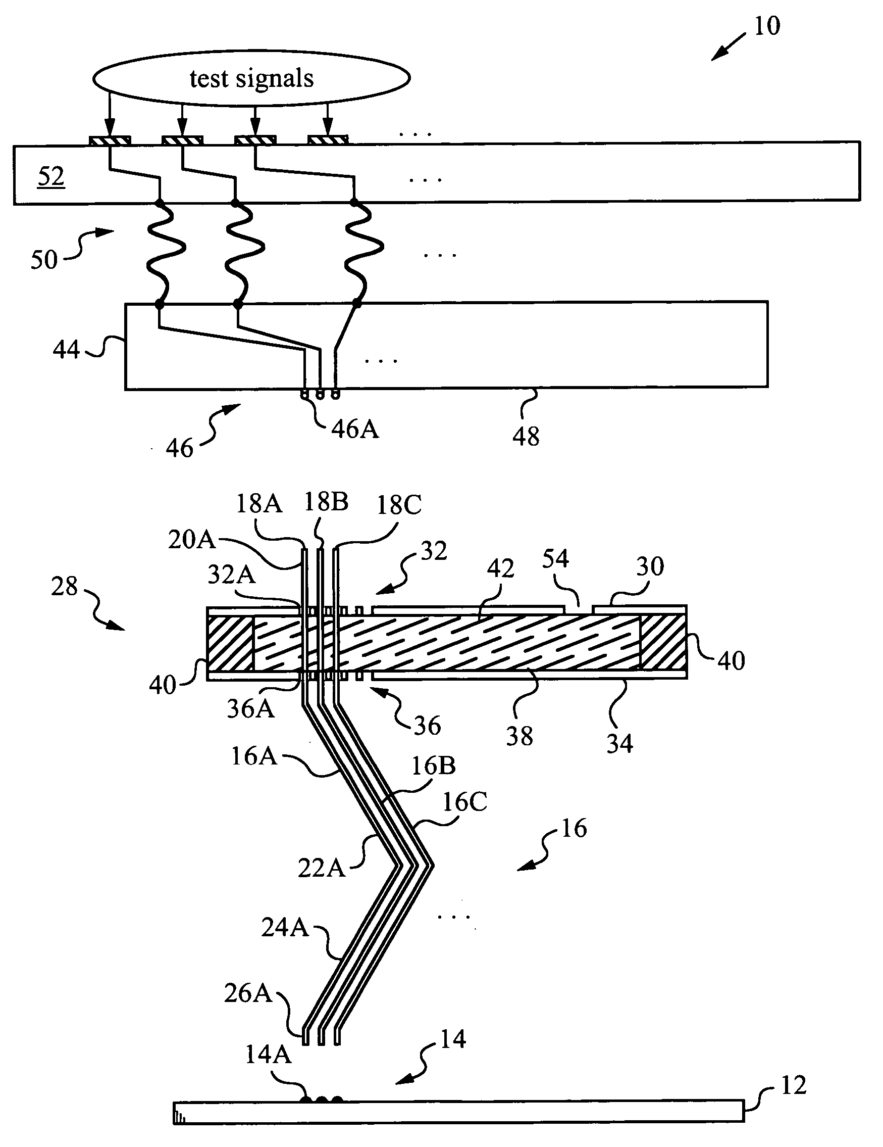
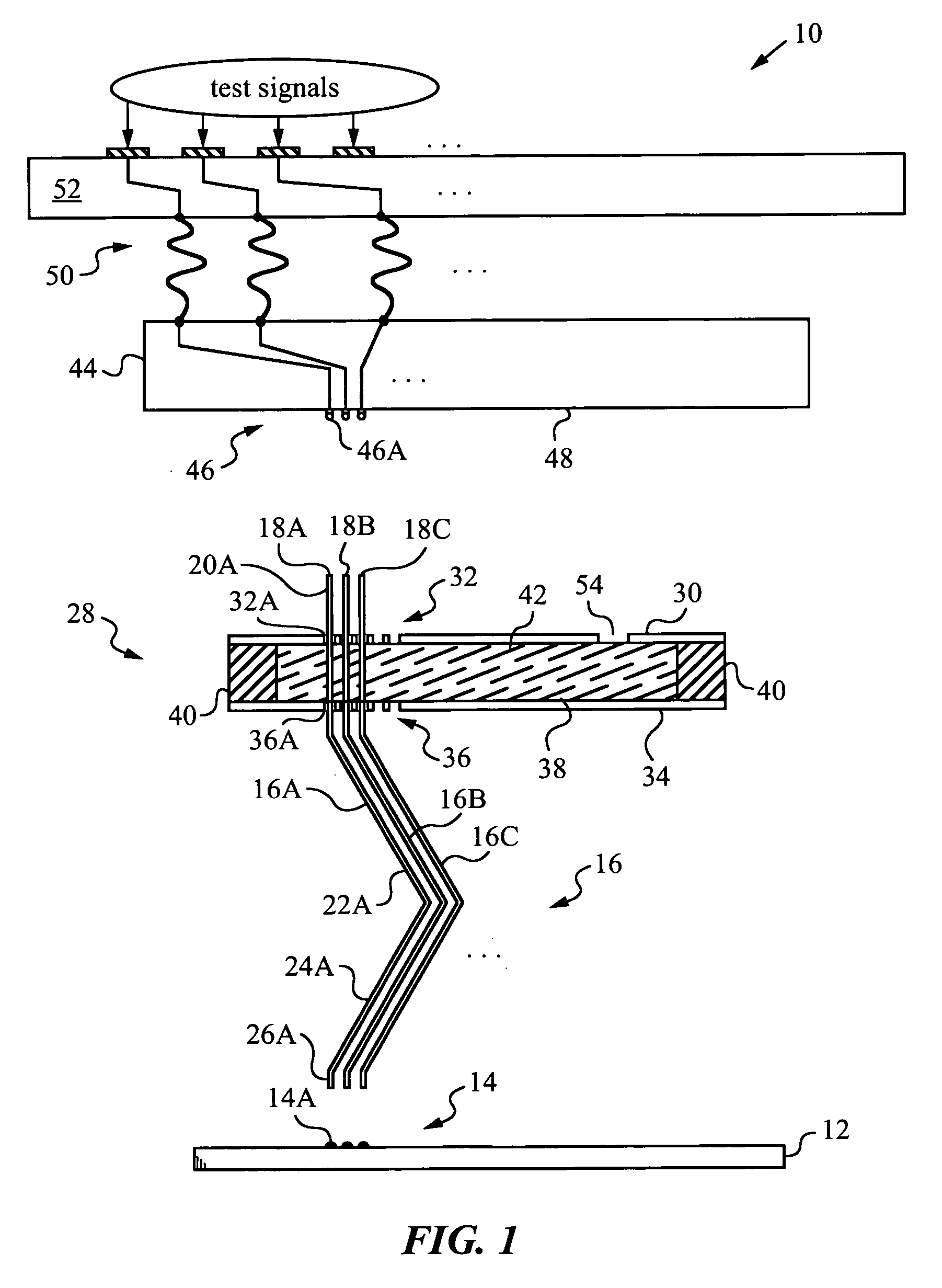
[0030] The present invention will be best understood by first reviewing an apparatus 10 of the invention as shown in the diagram of FIG. 1. Apparatus 10 can be employed in a probe card or other electrical testing equipment for testing a device under test (DUT) 12. Frequently, DUT 12 is an integrated circuit on a wafer that requires testing prior to dicing. Alternatively, DUT 12 is an electronic device or circuit that is already mounted. The functionality of DUT 12 is verified by applying test signals to a number of its bumps or pads 14.

[0031] Apparatus 10 has a number of probes 16 arranged in an array and designed for establishing electrical contact with pads or bumps 14. Typically, the number of probes 16 is large and their spacing or pitch is very small, e.g., on the order of several microns. For clarity, only three probes 16A, 16B, 16C are illustrated. The construction of all probes 16 is analogous and will be explained by referring explicitly to probe 16A.

[0032] Probe 16A has ...


PUM


Abstract

Method and apparatus using a retention arrangement with a potting enclosure for holding a plurality of probes by their retention portions, the probes being of the type having contacting tips for establishing electrical contact with pads or bumps of a device under test (DUT) to perform an electrical test. The retention arrangement has a top plate with top openings for the probes, a bottom plate with bottom openings for the probes, the plates being preferably made of ceramic with laser-machined openings, and a potting enclosure between the plates for admitting a potting agent that upon curing pots the retaining portions of the probes. In some embodiments a spacer is positioned between the top and bottom plates for defining the potting enclosure. Alternatively, the retention arrangement has intermediate plates located in the potting enclosure and having probe guiding openings to guide the probes.

Description

FIELD OF THE INVENTION [0001] This invention relates generally to apparatus and method for retaining probes in an electrical testing arrangement such as a probe card, and more specifically to potting of such probes in a retaining arrangement belonging to the probe card to ensure superior mechanical and electrical performance. Background Art [0002] The testing of semiconductor wafers and other types of integrated circuits (ICs), collectively known as devices under test (DUTs), needs to keep pace with technological advances. Each IC has to be individually tested, typically before dicing, in order to ensure that it is functioning properly. The demand for testing products is driven by considerations of new chip designs and higher volumes. [0003] In particular, chips are getting smaller and they have more tightly spaced contact pads. The pads are no longer located about the circuit perimeter, but in some designs may be found within the area occupied by the circuit itself. As a result, th...

Claims


Application Information

Patent Timeline
IPC IPC(8): G01R31/02
CPCG01R1/07357G01R1/07371
Inventor KISTER, JANUARY
Owner MICRO PROBE
Learn More