
Phosphor deposition method and apparatus for making light emitting diodes

a technology of light-emitting diodes and phosphor deposition methods, which is applied in the direction of electrical apparatus, basic electric elements, semiconductor devices, etc., can solve the problems of inability to meet the requirements of light-emitting applications, inability to meet the requirements of demanding applications, and large variability in white light spectrum from unit to uni

Inactive Publication Date: 2007-06-07
INNOVATIONS & OPTICS
View PDF9 Cites 38 Cited by
  • Summary
  • Abstract
  • Description
  • Claims
  • Application Information

AI Technical Summary

Benefits of technology

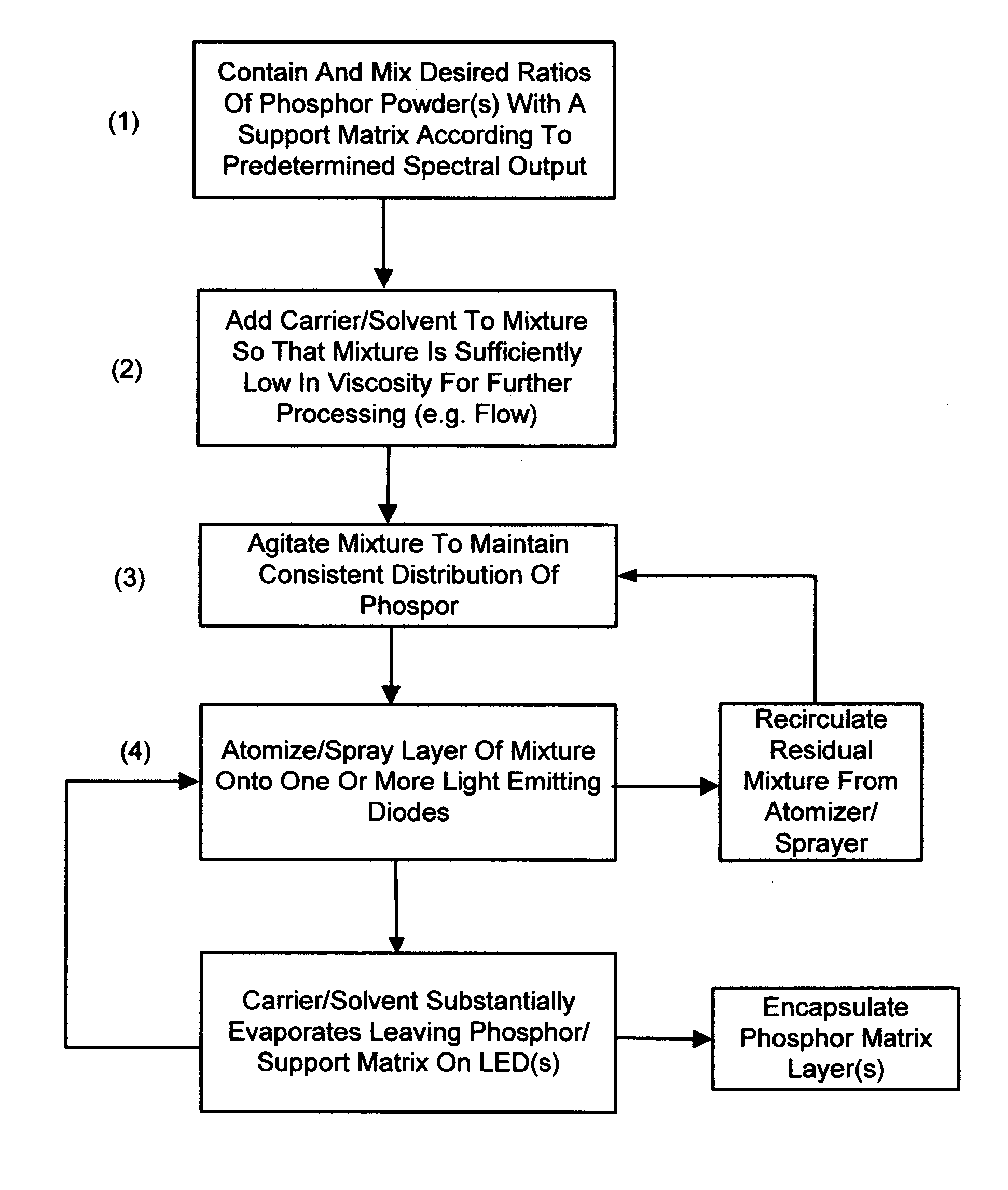
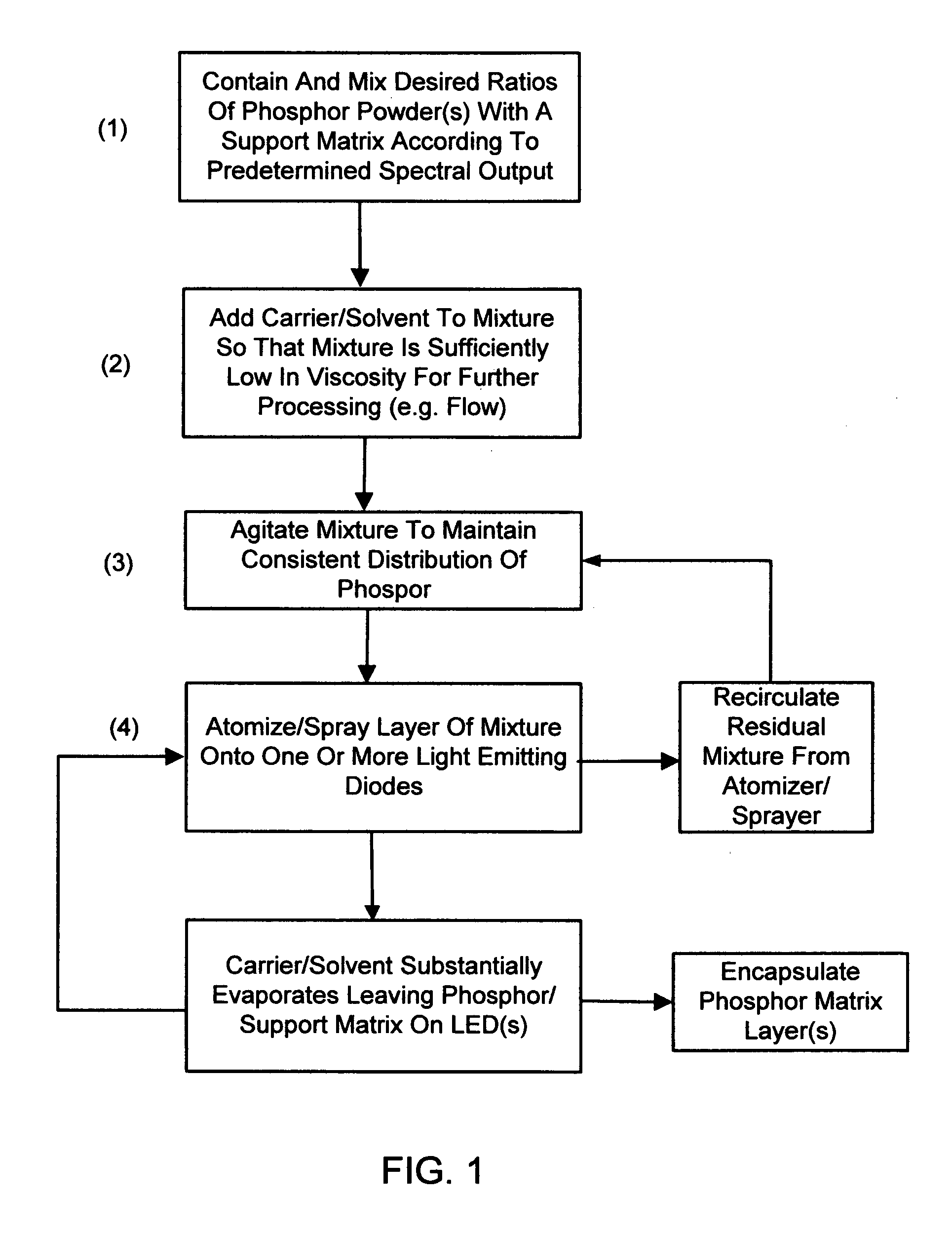
[0011] A carrier is then introduced into the phosphor powder matrix to decrease the viscosity of the mixture for further processing (e.g. pumping through distribution channels).
[0015] In another aspect of the invention, after deposition onto the LED(s), the one or more thin layers of phosphor are encapsulated onto the LED(s) with a thin transparent material that keeps the phosphor matrix layer(s) substantially stable and stationary on the LED(s).

Problems solved by technology

Unacceptable color consistency and uniformity are significant problems within the high brightness LED market because of the methods by which such LEDs are manufactured.
This effect occurs because of a non-uniformity in the thickness of the phosphor-containing material surrounding the LED and consequent spatially non-uniform absorption of blue light and emission of red and green light.
During processing (mixing, deposition, curing), the phosphor particles inconsistently settle within the mixture, leading to a large amount of variability in white light spectrum from unit to unit.
This results in both color and intensity nonuniformities thereby reducing the utility of the light source for demanding applications.

Method used


Image

  • Phosphor deposition method and apparatus for making light emitting diodes
  • Phosphor deposition method and apparatus for making light emitting diodes
  • Phosphor deposition method and apparatus for making light emitting diodes

Examples


Embodiment Construction

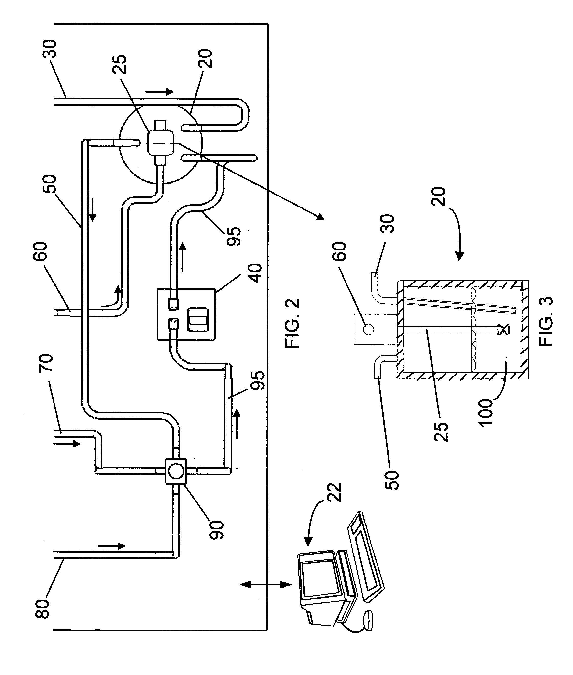
[0028] The present invention relates to apparatus and methods for depositing homogeneous mixture of a matrix and preselected phosphor powder mixture as a uniform layer on an LED chip to reduce variability in the color of radiation emitted by the resultant LED assembly. The structure and properties of the final LED product using the inventive methodology also forms part of the invention. The methodology may best be understood by now referring to FIG. 1 which identifies various high level steps practiced in implementing the method of the invention. The steps are generally carried out at ambient or room temperature. The first step is to contain and mix predetermined amounts of one or more phosphor powders associated with a predetermined spectral output when deposited on a specific LED device. To produce substantially white light with, for example, a 460 nm LED with a 30 nm bandwidth (FWHM), yellow emitting Yitrium Aluminum Oxide:Cerium powder is combined with red emitting Calcium Sulph...


PUM

PropertyMeasurementUnit
viscosityaaaaaaaaaa
FWHMaaaaaaaaaa
FWHMaaaaaaaaaa

Abstract

A phosphor deposition process and apparatus that enables an efficient, consistent, and flexible white light LED light engine by spraying a conformal coating of phosphor matrix onto an array of LEDs to achieve high color uniformity, consistency, and efficiency. A predetermined ratio of one or more phosphor powders are mixed with a support matrix (preferably silicone), the types and amounts of which are calculated to provide a predetermined spectral output. A low-viscosity carrier is introduced into the phosphor matrix to allow for further processing and deposition. The phosphor matrix and carrier mixture is atomized and sprayed in one or more uniform layers onto one or more LED devices. Computerized control, movable stages, and in-process spectral monitoring are incorporated to provide rapid and accurate processing of LED devices.

Description

FIELD OF THE INVENTION [0001] This invention, in general, relates to the manufacture of light emitting diodes, and in particular, to apparatus and methods by which one or more thin homogeneous phosphor layers can be uniformly applied to LED chips to control the color, brightness, and variability of radiation they emit BACKGROUND OF THE INVENTION [0002] Unacceptable color consistency and uniformity are significant problems within the high brightness LED market because of the methods by which such LEDs are manufactured. The most common method for making white light from an LED is by the deposition of phosphor onto a blue LED. When excited by a specific frequency of light, the phosphor has a broadband fluorescence emission into the green, yellow, and potentially, red regions of the light spectrum. The combination of blue light from the LED in conjunction with the emission spectrum from the phosphor results in white light. For example, U.S. Pat. Nos. 5,813,753 and 5,998,925 disclose lig...

Claims


Application Information

Patent Timeline
Patent Type & Authority Applications(United States)
IPC IPC(8): H01L21/00
CPCH01L21/6715H01L33/50H01L2933/0041
Inventor BRUKILACCHIO, THOMAS J.DEMILO, CHARLES A.DOYLE, DAVID A.WILLIAMSON, RYAN C.
Owner INNOVATIONS & OPTICS
Learn More