
Method for forming solder balls with a stable oxide layer by controlling the reflow ambient

a technology of oxide layer and process flow, which is applied in the direction of electrical equipment, semiconductor devices, printed circuits, etc., can solve the problems of inability to remove solder pads after deposition process, inability to meet the requirements of forming a solder layer, etc., to achieve enhanced stability and uniformity of corresponding tin, easy and efficient removal, and enhanced stability

Inactive Publication Date: 2007-05-31
GLOBALFOUNDRIES US INC
View PDF2 Cites 17 Cited by
  • Summary
  • Abstract
  • Description
  • Claims
  • Application Information

AI Technical Summary

Benefits of technology

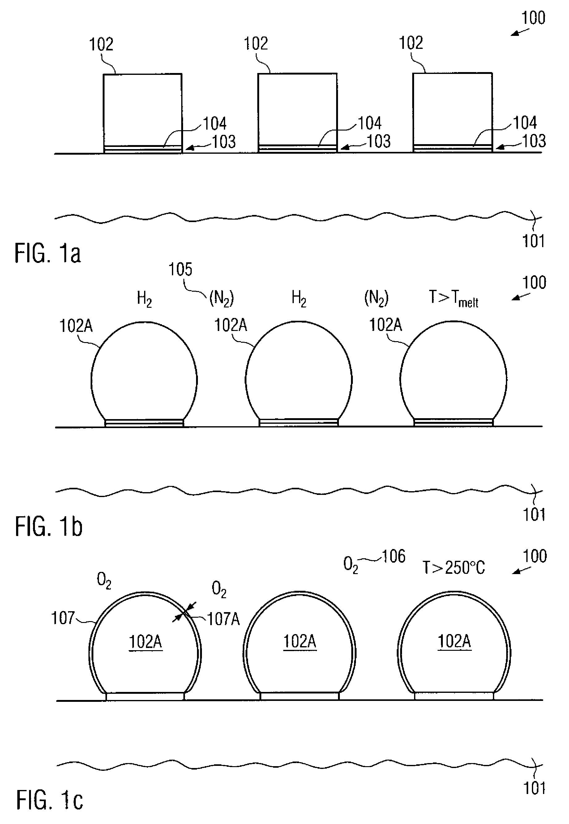
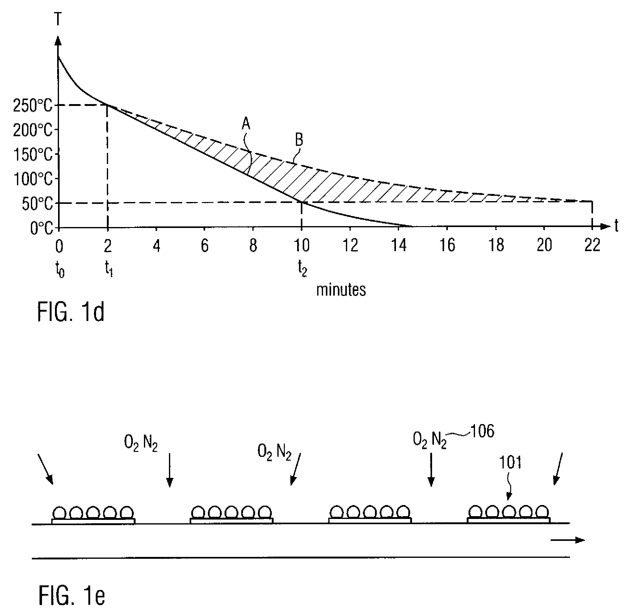
[0010] Generally, the present invention is directed to a technique that addresses uniformity issues of the reflow process that may be caused by the oxide passivation layer by enabling the formation of a reliable oxide layer on a surface area of solder balls, which has an enhanced stability, while a thickness and a uniformity thereof is improved so as to be readily and efficiently removed prior to and during the solder process for attaching a solder pad to respective solder balls. According to the present invention, the enhanced stability and uniformity of the corresponding tin and lead oxide-containing cover layer of the respective solder balls may be accomplished by appropriately controlling the temperature at which the oxidation process is initiated and / or the cooling rate during the formation of the oxide layer in an oxidizing ambient after the reflow process for rounding the initial solder bumps is completed.

Problems solved by technology

Moreover, it is extremely difficult to remove the metal mask after completion of the deposition process without damaging the solder pads, particularly when large wafers are processed or the pitch between adjacent solder pads is small.
Thus, the underbump metallization also has to meet strictly set constraints with respect to a uniform current distribution as any non-uniformities during the plating process may affect the final configuration of the bumps and, after reflowing, the bumps of the resulting solder balls in terms of, for instance, height non-uniformities, which may in turn translate into fluctuations of the finally obtained electric connections and the mechanical integrity thereof.
The height of the bumps is, among others, determined by the local deposition rate during the electroplating process, which is per se a highly complex process, so that process non-uniformities resulting from irregularities of the plating tool or any components thereof may also directly cause corresponding non-uniformities during the final assembly process.
During the removal of the oxide layer, however, non-removed residuals of the oxide may significantly affect the solder process, thereby possibly causing a non-wet contact with the solder pad of the carrier substrate.
Hence, a less reliable connection or a total failure of the connection may result.
As previously explained, great efforts are made for improving the complex process related to the formation of the underbump metallization layer and the solder bumps; however, non-uniformities encountered during the reflow process may be of comparable importance.

Method used


Image

  • Method for forming solder balls with a stable oxide layer by controlling the reflow ambient
  • Method for forming solder balls with a stable oxide layer by controlling the reflow ambient
  • Method for forming solder balls with a stable oxide layer by controlling the reflow ambient

Examples


Embodiment Construction

[0020] Illustrative embodiments of the invention are described below. In the interest of clarity, not all features of an actual implementation are described in this specification. It will of course be appreciated that in the development of any such actual embodiment, numerous implementation-specific decisions must be made to achieve the developers' specific goals, such as compliance with system-related and business-related constraints, which will vary from one implementation to another. Moreover, it will be appreciated that such a development effort might be complex and time-consuming, but would nevertheless be a routine undertaking for those of ordinary skill in the art having the benefit of this disclosure.

[0021] The present invention will now be described with reference to the attached figures. Various structures, systems and devices are schematically depicted in the drawings for purposes of explanation only and so as to not obscure the present invention with details that are we...


PUM

PropertyMeasurementUnit
temperatureaaaaaaaaaa

Abstract

By controlling the cooling rate during the oxidation process for forming an oxide layer on solder balls and by selecting an elevated temperature as an initial temperature of the oxidation process, a reliable yet easily removable oxide layer may be obtained. Consequently, yield losses during the flip chip assembly process may be significantly reduced.

Description

BACKGROUND OF THE INVENTION [0001] 1. Field of the Invention [0002] The present invention relates to a process flow for forming a solder layer including contact balls of a contact material, such as solder, for providing contact areas for directly attaching an appropriately formed package or carrier substrate to a die carrying an integrated circuit. [0003] 2. Description of the Related Art [0004] In manufacturing integrated circuits, it is usually necessary to package a chip and provide leads and terminals for connecting the chip circuitry with the periphery. In some packaging techniques, chips, chip packages or other appropriate units may be connected by means of balls of solder or any other conductive material, formed from so-called solder bumps, that are formed on a corresponding layer, which will be referred to herein as a solder layer, of at least one of the units, for instance on a dielectric passivation layer of the microelectronic chip. In order to connect the microelectronic...

Claims


Application Information

Patent Timeline
Patent Type & Authority Applications(United States)
IPC IPC(8): H01L21/44
CPCH01L24/11H01L2224/81011H01L24/81H01L2224/1147H01L2224/13099H01L2224/13111H01L2224/81801H01L2924/01002H01L2924/01018H01L2924/01029H01L2924/01078H01L2924/01082H01L2924/01327H01L2924/14H01L2924/19041H01L2924/19042H01L2924/19043H05K3/3457H05K3/3494H05K2203/0315H05K2203/043H05K2203/086H01L2924/01005H01L2924/01006H01L2924/01033H01L2924/01068H01L2924/014H01L24/742H01L24/05H01L2224/05001H01L2224/05023H01L2224/0508H01L2224/051H01L2224/05568H01L2224/05647H01L2224/10125H01L2224/118H01L2924/00014
Inventor JUNGNICKEL, GOTTHARDPLATZ, ALEXANDERKUECHENMEISTER, FRANK
Owner GLOBALFOUNDRIES US INC
Learn More