
Multi-chamber container

a multi-chamber, container technology, applied in the field of containers, can solve the problems of poor heat resistance of polymer compositions, unsuitable sterilization, broken or deformation of containers, etc., and achieve the effect of optimal and stable seal strength, good clarity, and easy adjustment and free movemen

Active Publication Date: 2007-05-24
FUJIMORI KOGYO CO LTD
View PDF6 Cites 25 Cited by
  • Summary
  • Abstract
  • Description
  • Claims
  • Application Information

AI Technical Summary

Benefits of technology

The present invention is a new type of compartmented container that can hold two or more contents separately in individual compartments. The container is made from a resin film or sheet with a heat-sealable layer on at least one side. The heat-sealable layer is made from a composition of propylene copolymers composed of propylene and ethylene and / or C4-8 α-olefin. The container has good heat resistance and can withstand sterilization at 121°C. The container is also transparent and has good seal strength. The technical effects of this invention include high heat resistance, seal strength, and good clarity.

Problems solved by technology

Therefore, this seal layer is likely to soften during sterilization at 121° C., resulting in breakage or deformation of the container.
This tape is formed from a mixture of polyethylene and polypropylene, and hence it is unsuitable for sterilization at 121° C. as in the case of Patent Documents 1 and 2.
These polymer compositions are poor in heat resistance because of a high content of α-olefin and elastomer and hence are unsuitable for sterilization at 121° C.
An excessively high seal strength rather makes the weakly sealed part take a long time to break.
The weakly sealed part needs a high seal strength because the container is large and the weakly sealed part is subject to a large load at the time of dropping.
The weakly sealed part with an excessively low seal strength is likely to break due to the heavy load.
Unfortunately, the range of change that can be achieved is limited to only about 20° C.

Method used


Image

  • Multi-chamber container
  • Multi-chamber container
  • Multi-chamber container

Examples


example 1

[0094] A sheet 1 with a total thickness of 200 μm, which consists of a surface layer with a thickness of 20 μm, an intermediate layer with a thickness of 140 μm, and a heat-sealable layer with a thickness of 40 μm, was prepared by multi-layer coextrusion from the following materials.

[0095] Material for the surface layer: A composition composed of component (a) defined below and propylene homopolymer in a ratio of 9:1.

[0096] Material for the intermediate layer: A composition composed of component (a) defined below and metallocene plastomer (“Kernel” from Japan Polychems, Inc.) having a tensile modulus of 100 MPa in a ratio of 8:2.

[0097] Material for the heat-sealable layer: A composition composed of component (a) defined below and component (b) defined below in a ratio of 6:4.

[Component (a)]

[0098] A reactor-type propylene-based TPO (Thermoplastic Olefin Elastomer) (from Mitsubishi Chemical Corporation), which gives such a specific ratio of the amount of elution measured by the t...

example 2

[0102] A sheet 2 with a total thickness of 200 μm, which consists of a surface layer with a thickness of 20 μm, an intermediate layer with a thickness of 140 μm, and a heat-sealable layer with a thickness of 40 μm, was prepared by multi-layer coextrusion from the following materials.

[0103] Material for the surface layer: A composition composed of component (a) defined above and propylene homopolymer in a ratio of 9:1.

[0104] Material for the intermediate layer: A composition composed of component (a) defined above and a styrene-based elastomer containing 20% styrene (“Hybrar” from Kuraray Co., Ltd.) in a ratio of 9:1.

[0105] Material for the heat-sealable layer: A composition composed of component (a) defined above and component (b) defined above in a ratio of 7:3.

[0106] The thus obtained sheet 2 was heat-sealed at 200° C. and 0.5 MPa for 4 seconds to form the peripheral sealed part and the port sealed part. Then it was heat-sealed at 160° C. and 0.2 MPa for 2 seconds to form the ...

example 3

[0108] A sheet 3 with a total thickness of 250 μm, which consists of a surface layer with a thickness of 20 μm, an intermediate layer with a thickness of 180 μm, and a heat-sealable layer with a thickness of 50 μm, was prepared by multi-layer coextrusion from the following materials.

[0109] Material for the surface layer: A composition composed of component (a) defined above, component (b) defined above, and propylene homopolymer in a ratio of 8:1:1.

[0110] Material for the intermediate layer: A composition composed of component (a) defined above, component (b) defined above, and a metallocene plastomer (“Kernel” from Japan Polychems, Inc.) having a tensile modulus of 80 MPa in a ratio of 6:2:2.

[0111] Material for the heat-sealable layer: A composition composed of component (a) defined above and component (b) defined above in a ratio of 7:3.

[0112] The thus obtained sheet 3 was heat-sealed at 210° C. and 0.5 MPa for 4 seconds to form the peripheral sealed part and the port sealed p...


PUM

PropertyMeasurementUnit
temperaturesaaaaaaaaaa
total light transmittanceaaaaaaaaaa

Abstract

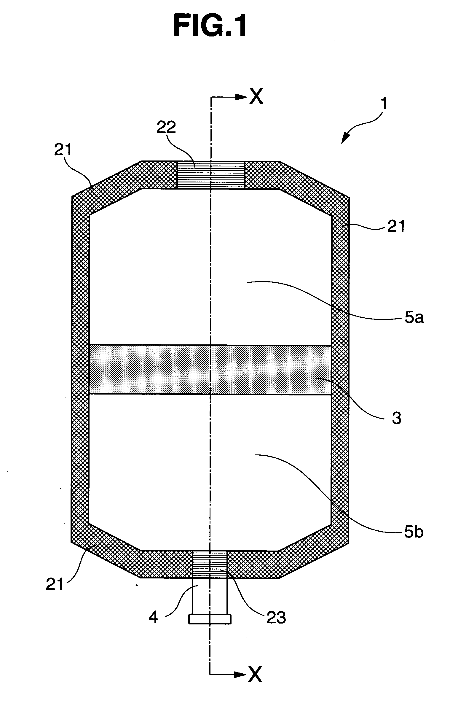
Multi-chamber container (1) having its interior partitioned by weak seal portions (3) provided through detachable heat sealing so that multiple contents are accommodated separately from each other, wherein use is made of heat seal layers consisting of a composition comprising two types of propylene copolymers components (component A and component B) from propylene and ethylene and / or a C4-C8 α-olefin which have the following elution properties. Thus, a region wherein a change of seal strength by a change of heat seal temperature is small has a wide temperature range to thereby facilitate controlling of the seal strength at the weak seal portions. The proportion (mass %) of, to total solution, elution according to the TREF method (temperature: 0 to 140° C. and solvent: ODCB) is as follows. With respect to component A: 15 to 50 at 0° C., and 5 to less than 15 at 60 to 90° C. With respect to component B: 0 to 25 at 0° C., and 15 to 70 at 60 to 90° C.

Description

TECHNICAL FIELD [0001] The present invention relates to a compartmented container with two or more compartments isolated from each other by a weakly sealed part (separator) which can be broken for internal mixing of contents in individual compartments at the time of their use. The weakly sealed part has a seal strength that can be adjusted easily, and the container also withstands sterilization at 121° C. BACKGROUND ART [0002] It is common practice in the medical field to use a medicinal container holding plural ingredients separately which are to be mixed immediately before administration. For example, a transfusion solution for IVH (intravenous hyperalimentation), which is composed of carbohydrate, amino acid, and electrolyte as a nutrient source, is stored in a compartmented container holding individual ingredients in separate compartments, thereby protecting glucose and amino acid from deterioration by Maillard reaction, and these ingredients are mixed together immediately befor...

Claims


Application Information

Patent Timeline
Patent Type & Authority Applications(United States)
IPC IPC(8): B65D25/08B65D73/00A61J1/00A61J1/05B65D81/32A61J1/10A61J1/20B32B27/32B65D75/58
CPCB65D81/3266A61J1/10A61J1/2093A61J2001/2024A61M2207/00B32B27/08Y10T428/1334B32B2250/242B32B2307/31B32B2307/5825B32B2439/40B65D75/5883Y10T428/1352B32B27/32A61J1/2024
Inventor SUZUKI, TOYOAKIMIURA, KOICHITAKAYANAGI, KENJIRO
Owner FUJIMORI KOGYO CO LTD
Learn More