
Polymeric hollow fiber heat exchange systems

Inactive Publication Date: 2007-05-17
NEW JERSEY INSTITUTE OF TECHNOLOGY
View PDF13 Cites 82 Cited by
  • Summary
  • Abstract
  • Description
  • Claims
  • Application Information

AI Technical Summary

Benefits of technology

[0016] The present disclosure provides advantageous heat exchange systems that include one or more asymmetric polymeric solid hollow fibers. Exemplary asymmetric polymeric solid hollow fibers according to the present disclosure are characterized by hollow fibers that include a microporous wall and a dense skin formed thereon, thereby preventing liquid transmission and / or contamination through the wall of the hollow fiber while simultaneously enhancing heat transfer based on the presence of liquid molecules within the porous substructure of the hollow fiber. The disclosed asymmetric hollow fibers may be employed in a variety of heat transfer-related commercial / industrial applications, including desalination applications, solar heating applications, applications in the chemical industry, and applications in the biotechnology or pharmaceutical industry. For example, the disclosed asymmetric polymeric solid hollow fibers may find advantageous application in extracorporeal blood oxygenation systems with the heat exchange fluid on the porous wall side.
[0017] In addition, the present disclosure provides heat transfer systems wherein steam is advantageously condensed on a first side of a polymeric, hollow fiber-based heat exchanger. The condensed steam provides energy that may be used to heat water and / or other liquids that flow on a second side of the polymeric, hollow fibers. Indeed, by using a steam feed that is adapted to condense on one side of the hollow fibers (rather than a gas) and a liquid on the other side, overall heat transfer coefficients on the order of a liquid-liquid heat exchanger can be achieved with the disclosed heat transfer system (if not higher). According to exemplary embodiments of the disclosed steam condensation heat transfer systems, a hydrophobic polymeric surface (e.g., polypropylene) may effect drop-wise condensation of the steam, thereby enhancing the overall heat transfer performance of the disclosed systems. Condensation of the steam is generally effected to form relatively small droplet sizes, thereby minimizing the likelihood of condensation-related flow restriction on the steam side of the hollow fiber system.
[0018] Of note, the disclosed polymeric hollow fibers offer numerous industrial advantages. For example, the polymeric hollow fibers disclosed herein are substantially inert to a wide range of processing fluids / systems, e.g., brine-to-brine, brine-to-water, and steam-to-brine desalination applications. The polymeric hollow fibers are not susceptible to corrosion and / or erosion (which can limit the utility of metal heat exchange tubes), and may be fabricated in highly compact designs. Highly compact designs are feasible, at least in part, because the disclosed polymeric hollow fibers have a very high surface area per unit equipment volume (as compared to non-polymeric heat exchange systems or even other plastic heat exchange systems). Thus, an equivalent volume may be an order of magnitude smaller, thereby drastically reducing the associated system weight, footprint and cost.

Problems solved by technology

Indeed, polymeric hollow fibers fabricated from such exemplary polymeric systems as polypropylene, polyethersulfone (PES), polyetheretherketone (PEEK), polyimides, polyphenylene sulfide (PPS), polyethylene (PE), polytetrafluoroethylene (PTFE), polysulfone (PS), poly-4-methyl-1-pentene (PMP) and the like, are generally unaffected by hot brine, cold brine, pH values over a wide range, a host of chemical systems, and a host of solvents.

Method used


Image

  • Polymeric hollow fiber heat exchange systems
  • Polymeric hollow fiber heat exchange systems
  • Polymeric hollow fiber heat exchange systems

Examples


Embodiment Construction

)

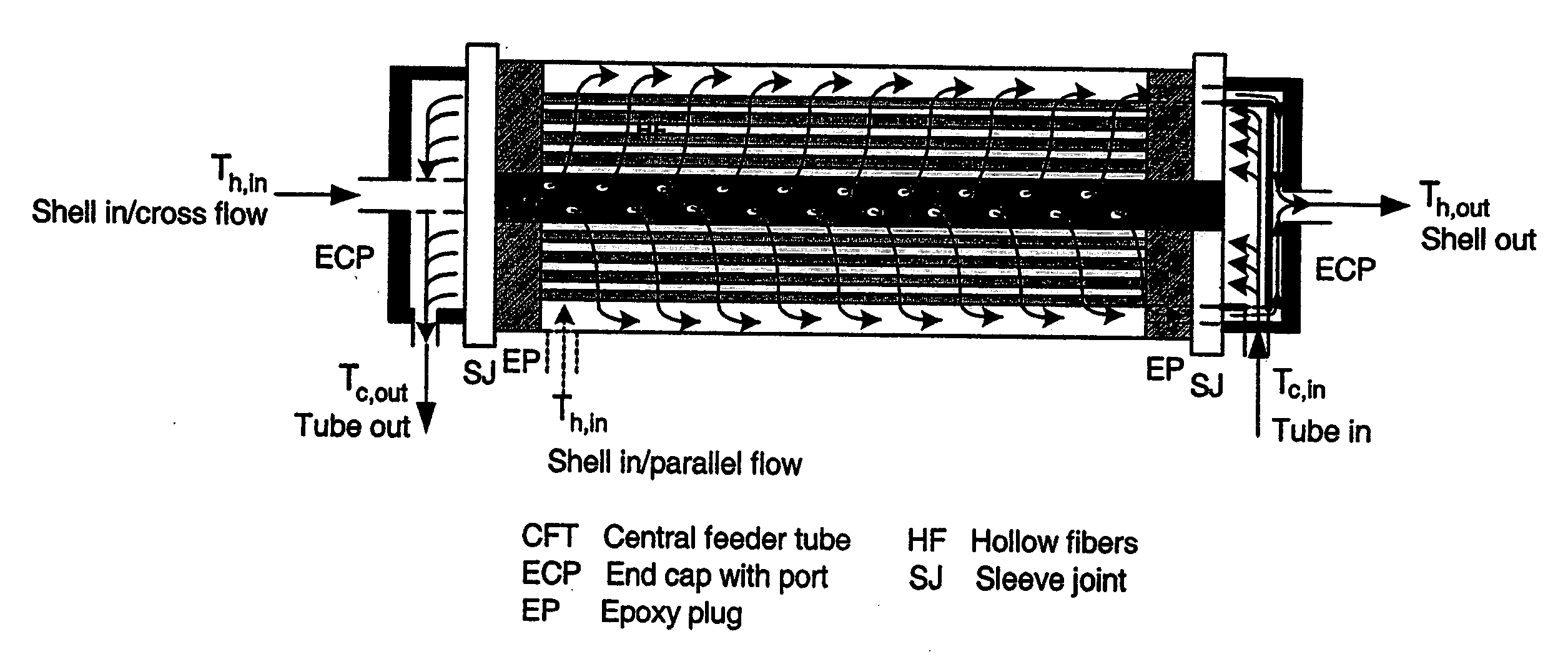
[0046] As noted above, the present disclosure provides advantageous heat exchange systems that include one or more polymeric solid hollow fibers and, more particularly, asymmetric porous hollow fiber heat exchange systems that provide enhanced heat transfer in a variety of applications, e.g., desalination applications, solar heating applications, applications in the chemical industry, applications in the biomedical industry and / or applications in the biotechnology industry. Exemplary embodiments of the disclosed heat exchange systems are characterized by hollow fibers that include a microporous wall and a dense skin formed thereon, thereby preventing liquid transmission and / or contamination through the wall of the hollow fiber while simultaneously enhancing heat transfer based on the presence of liquid molecules within the porous substructure of the hollow fiber. The disclosed heat exchange systems advantageously provide improved processing performance and reduced cost for industri...


PUM

PropertyMeasurementUnit
Thicknessaaaaaaaaaa
Diameteraaaaaaaaaa
Structureaaaaaaaaaa

Abstract

Heat exchange systems are provided that include one or more polymeric hollow fibers. Exemplary hollow fibers are asymmetric and include a microporous wall and a dense skin formed thereon, thereby preventing liquid transmission and / or contamination through the wall of the hollow fiber while simultaneously enhancing heat transfer based on the presence of liquid molecules within the porous substructure of the hollow fiber. The hollow fibers may be employed in a variety of heat transfer-related commercial / industrial applications, including solvent-aqueous systems, organic-aqueous systems, organic-organic systems, desalination applications, solar heating applications, applications in the chemical industry, applications in the biomedical industry, and applications in the biotechnology or pharmaceutical industry, e.g., extracorporeal blood oxygenation systems. Heat transfer systems wherein steam is advantageously condensed on a first side of a polymeric, hollow fiber-based heat exchanger are also provided. The condensed steam provides energy that may be used to heat water and / or other liquids that flow on a second side of the polymeric, hollow fibers.

Description

CROSS-REFERENCE TO RELATED APPLICATION(S) [0001] The present application claims the benefit of a co-pending provisional patent application entitled “Polymeric Hollow Fiber Heat Exchange Systems,” which was filed on Oct. 27, 2005 and assigned Ser. No. 60 / 730,954. The entire contents of the foregoing provisional patent application are incorporated herein by reference.BACKGROUND [0002] 1. Technical Field [0003] The present disclosure is directed to advantageous heat exchange systems that include one or more polymeric solid hollow fibers and, more particularly, asymmetric porous hollow fiber-based heat exchange systems that provide enhanced heat transfer in a variety of applications, e.g., desalination applications, solar heating applications, applications in the chemical industry, and / or applications in the biotechnology, biomedical or pharmaceutical industry. Exemplary embodiments of the disclosed heat exchange systems are characterized by hollow fibers that include a microporous wall...

Claims


Application Information

Patent Timeline
IPC IPC(8): F28F13/18
CPCF28D7/1669F28F21/062
Inventor SIRKAR, KAMALESH K.KORIKOV, ALEXANDER P.KOSARAJU, PRAVEEN B.ZARKADAS, DIMITRIOS
Owner NEW JERSEY INSTITUTE OF TECHNOLOGY
Learn More