
Level shifter apparatus and method for minimizing duty cycle distortion

a shifter and duty cycle technology, applied in the direction of logic circuit coupling/interface arrangement, pulse manipulation, pulse technique, etc., can solve the problems of large mismatch between power supply voltages between two domains, severe duty cycle errors, and error worsening, so as to minimize duty cycle distortion and high operating frequency

Inactive Publication Date: 2007-05-10
ELECTRONICS COMPONENTS TOSHIBA AMERICA +1
View PDF14 Cites 23 Cited by
  • Summary
  • Abstract
  • Description
  • Claims
  • Application Information

AI Technical Summary

Benefits of technology

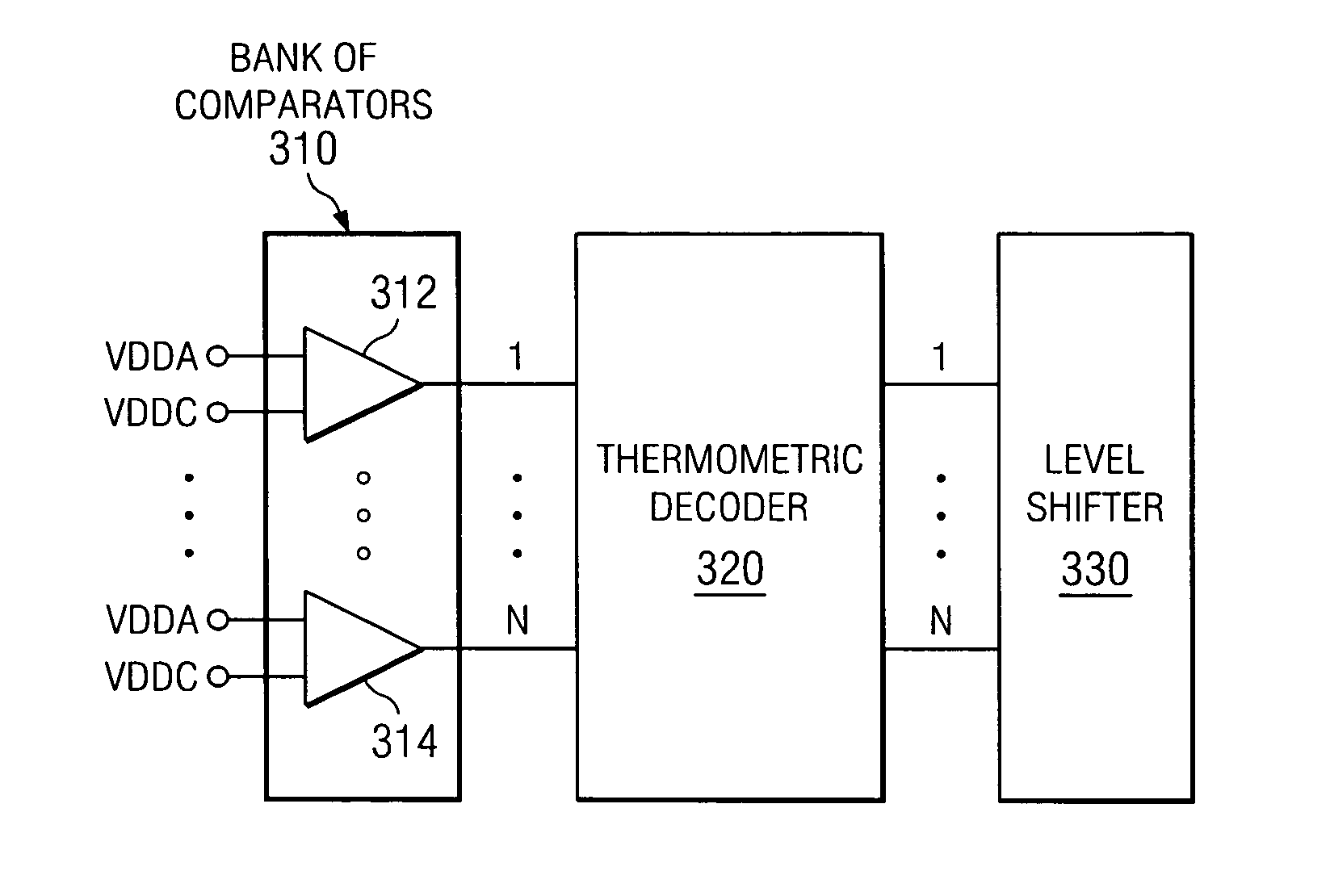
[0017] In view of the above, it would be beneficial to have a level shifter that can compensate for the duty cycle distortion as well as the limit on operating frequency introduced as a result of the VDDA−VDDC voltage mismatches. The illustrative embodiments provide such a level shifter mechanism for minimizing duty cycle distortion while achieving high operating frequency.
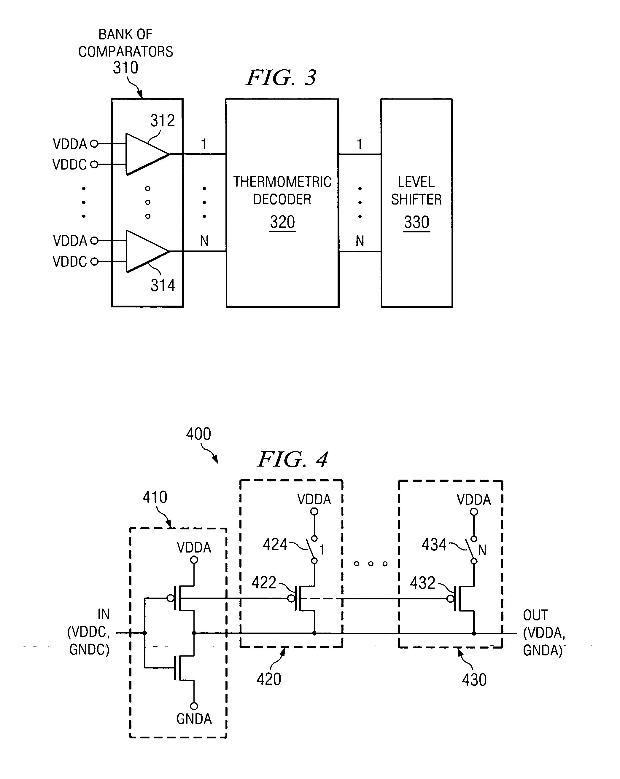
[0019] The output of this bank of N comparators is input to a second main portion of the level shifter mechanism comprising a N-to-N thermometric decoder. The N-to-N thermometric decoder ensures that drive strengths of the level shifter pull-up / down devices are increased and / or decreased monotonically. The N-to-N thermometric decoder converts the N input signals generated by the bank of comparators into N switch control signals as well as helps to eliminate non-linearities arising from, for example, comparator mismatches and the like. These switch control signals are output to a level shifter, providing in a third main portion of the level shifter mechanism, and are used to turn on / off current branches in stages of the level shifter, thereby increasing / decreasing the drive strengths of the pull-up / down devices of the level shifter. That is, the outputs of the thermometric decoder may either close or open switches in a series of stages of the current branches of the level shifter to thereby cause the pull-up / down devices of those stages to operate on the output of the inverter of the level shifter. In this way, the drive strengths of the pull-up / down devices in the level shifter are either increased or decreased.
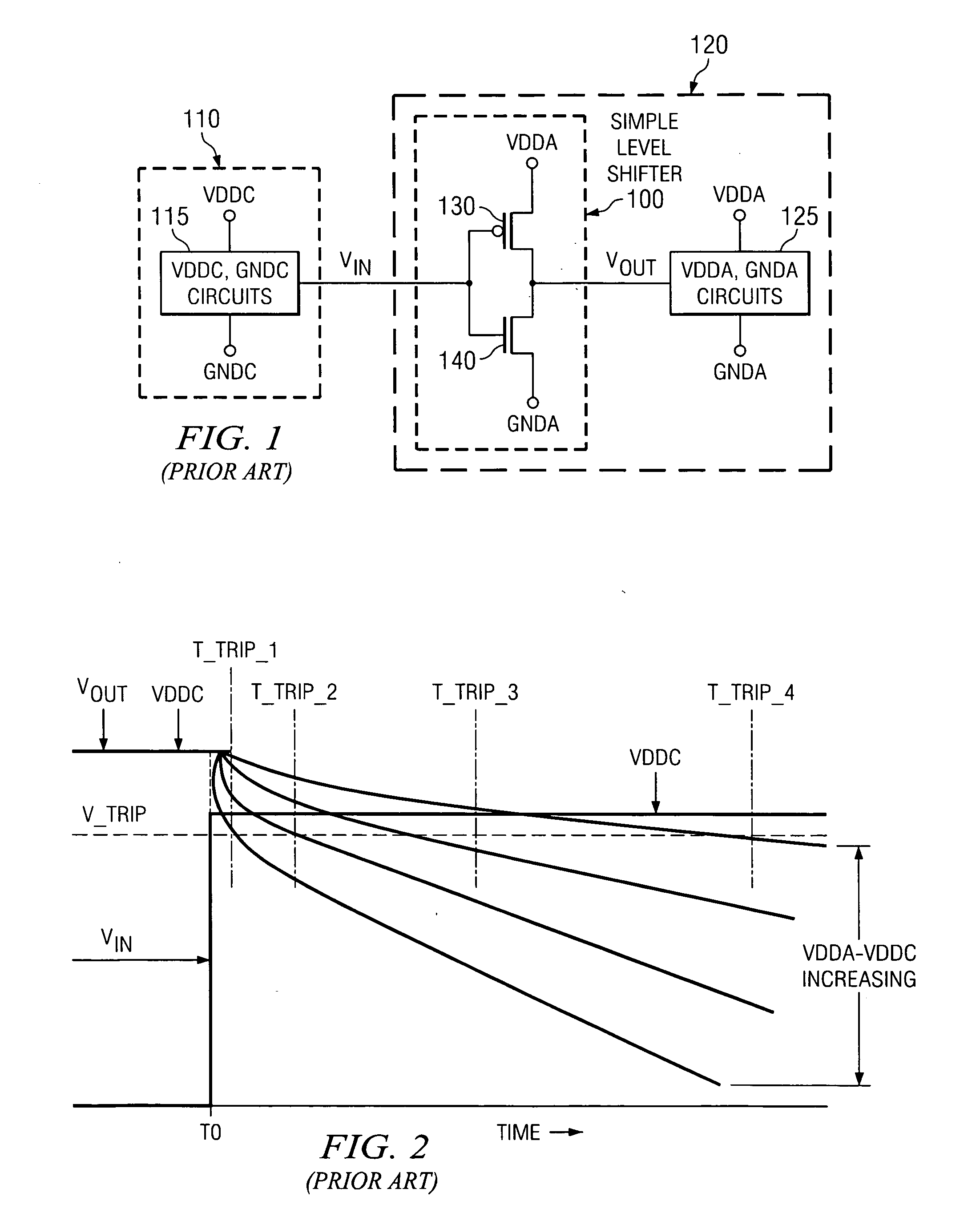
[0020] Thus, based on the voltage difference amount between the two power domains, pull-up / down devices in stages of a level shifter may be enabled to thereby boost or reduce the output voltage of the inverter in the level shifter. In so doing, the T_TRIP value for achieving an V_TRIP output voltage is reduced. Since T_TRIP is reduced by operation of the illustrative embodiments, the maximum frequency of operation of the circuit is increased (see equation 6 above).
[0022] In one illustrative embodiment, an apparatus is provided for minimizing duty cycle distortion. The apparatus may comprise at least one comparator that compares a difference between a source voltage of a first power domain and a source voltage of a second power domain, to at least one threshold built into the at least one comparator. The apparatus may further comprise a level shifter coupled to the at least one comparator. The level shifter may include an inverter and at least one stage that operates on a voltage output of the inverter when enabled. The at least one comparator may output at least one signal indicative of whether the at least one threshold is exceeded by the difference. The at least one signal may be used to control enabling of the at least one stage of the level shifter.
[0027] In another illustrative embodiment, a method for minimizing duty cycle distortion is provided. The method may be implemented in a data processing device and may comprise comparing, using at least one comparator, a difference between a source voltage of a first power domain and a source voltage of a second power domain, to at least one threshold. The method may further comprise controlling enabling of at least one stage in a level shifter coupled to the at least one comparator based on results of the comparing indicating that at least one threshold of the at least one threshold is exceeded by the difference. The level shifter may include an inverter and each stage in the at least one stage may operate on an output of the inverter when enabled. The data processing device may be part of a toy, a game machine, a game console, a hand-held computing device, a personal digital assistant, a communication device, a wireless telephone, a laptop computing device, a desktop computing device, or a server computing device.

Problems solved by technology

However, the voltage mismatch between the two power domains may cause severe duty cycle errors if simple receivers are used for level shifting.
This error gets worse as the mismatch in the power supply voltages between the two domains gets larger.
However, these known level shifter circuits do not address the issues arising due to high frequency operation.

Method used


Image

  • Level shifter apparatus and method for minimizing duty cycle distortion
  • Level shifter apparatus and method for minimizing duty cycle distortion
  • Level shifter apparatus and method for minimizing duty cycle distortion

Examples


Embodiment Construction

[0040] The illustrative embodiments provide a level shifter mechanism for converting a first input voltage signal to a second output voltage signal while compensating for duty cycle distortion and increasing the maximum operating frequency of the circuit. The level shifter mechanism of the illustrative embodiments performs such compensation by enabling various pull-up / down devices of stages of a level shifter based on a determined difference between the voltages of the two power domains. The various pull-up / down devices of the stages of the level shifter are enabled such that a monotonically increasing pull-up / down device drive strength is obtained which reduces the time for tripping a state change of the circuitry being driven by the level shifter mechanism.

[0041]FIG. 3 is an exemplary block diagram illustrating a level shifter circuit in accordance with an illustrative embodiment. As shown in FIG. 3, the level shifter mechanism of the illustrative embodiment includes a bank of N ...


PUM


Abstract

A level shifter apparatus and method for minimizing duty cycle distortion are provided. The level shifter includes a bank of comparators each having an associated threshold built into it. The comparators compare a difference in source voltages for two power domains to these built-in thresholds and output a signal indicative of whether the threshold is exceeded. The output signals from the comparators are provided to a thermometric decoder which generates control signals based on these output signals. The control signals are used to control stages in a level shifter for modifying the voltage output of the level shifter. Individual stages may be enabled to thereby monotonically modify the voltage output of the level shifter and thereby decrease a time required to achieve a voltage having a level that causes a state change in a driven circuit. As a result, duty cycle distortion is minimized and maximum operational frequency is increased.

Description

BACKGROUND [0001] 1. Technical Field [0002] The present application relates generally to an improved integrated circuit apparatus and method. More specifically, the present application is directed to a level shifter apparatus and method for minimizing duty cycle distortion. [0003] 2. Description of Related Art [0004] Level shifters are integral components of any circuit that operates from different power supply boundaries. The level shifters act as the interfaces between these different power supply domains to send / receive signals across these boundaries. However, the voltage mismatch between the two power domains may cause severe duty cycle errors if simple receivers are used for level shifting. This error gets worse as the mismatch in the power supply voltages between the two domains gets larger. To appreciate this, a simple explanation of how a simple level shifter works is provided below. [0005]FIG. 1 illustrates a simple level shifter in accordance with a known implementation. ...

Claims


Application Information

Patent Timeline
IPC IPC(8): H03K3/017
CPCH03K19/018521
Inventor BOERSTLER, DAVID W.HAILU, ESKINDERMIKI, KAZUHIKOQI, JIEMING
Owner ELECTRONICS COMPONENTS TOSHIBA AMERICA
Learn More