Eureka AIR delivers breakthrough ideas for toughest innovation challenges, trusted by R&D personnel around the world.

Direct conversion of nanoscale thermal radiation to electrical energy using pyroelectric materials

a technology of pyroelectric materials and nano-scale thermal radiation, which is applied in the direction of generators/motors, thermoelectric devices with dielectric constant thermal change, electric devices, etc., can solve the problems of low-grade waste heat, difficult to reuse, and significant energy resource consumption loss, so as to enhance the radiative heat flux, minimize both friction on the oscillating pe plate and heat loss to the surrounding.

Inactive Publication Date: 2011-12-08
RGT UNIV OF CALIFORNIA
View PDF2 Cites 35 Cited by
  • Summary
  • Abstract
  • Description
  • Claims
  • Application Information

AI Technical Summary

Benefits of technology

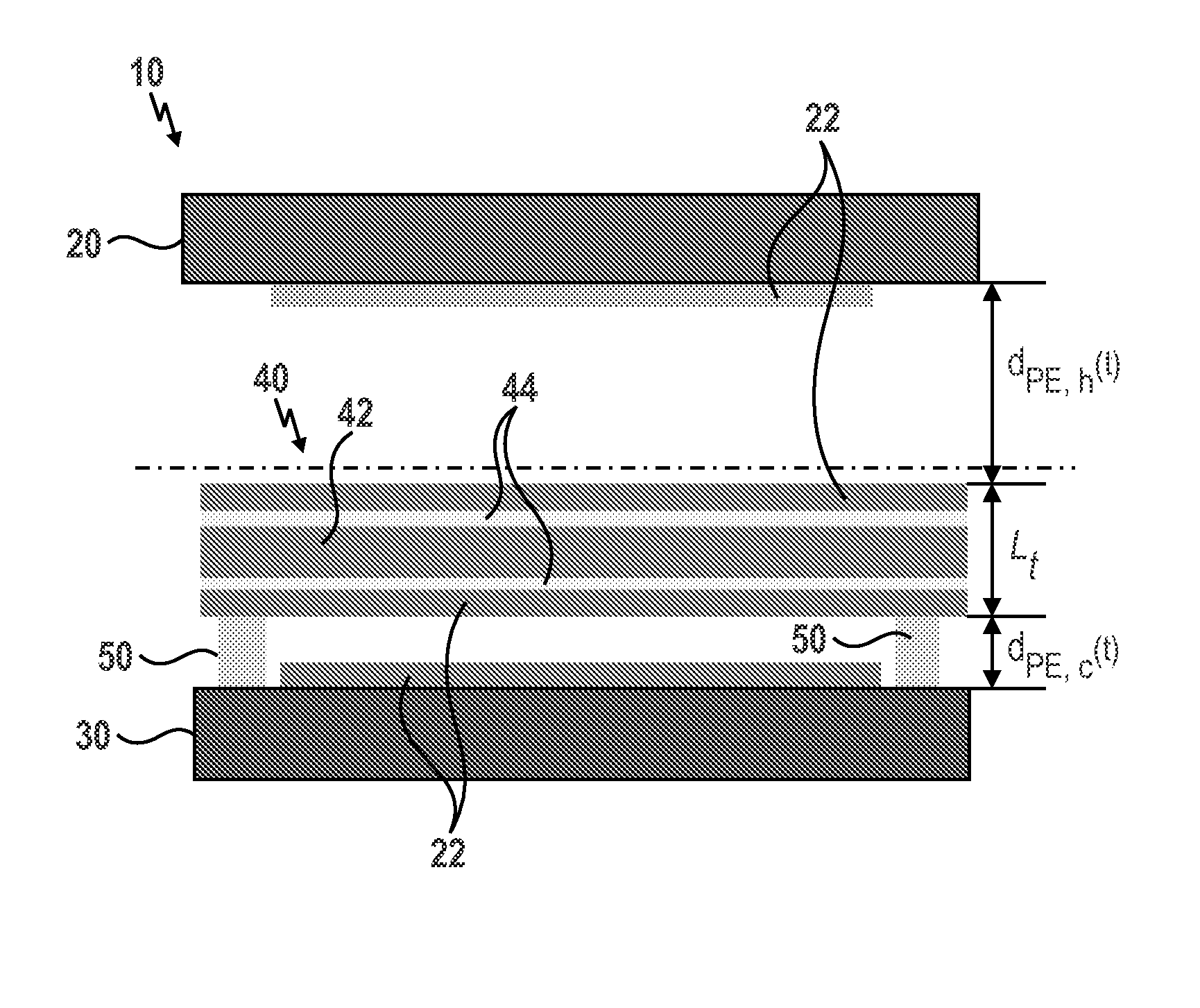
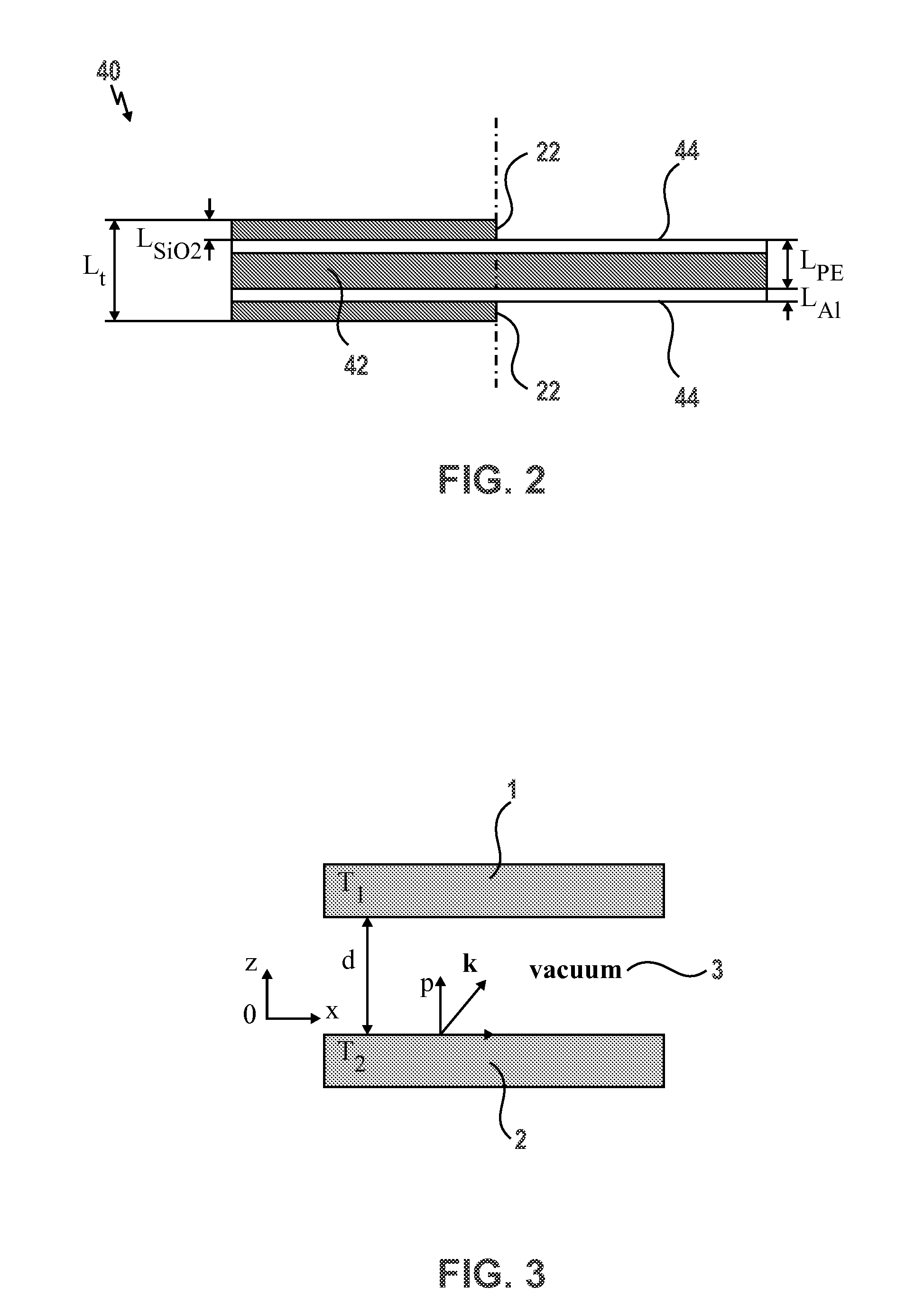
[0010]In fact, thermal radiative heat transfer takes place at the speed of light. In addition, the net radiation flux in vacuum between two surfaces at different temperatures can be increased by several orders of magnitude if they are separated by a distance comparable to or smaller than the characteristic wavelength given by Wien's displacement law. Thus, nanoscale radiative heat transfer has the potential to increase the operating frequency of pyroelectric energy converters, resulting in a larger power density and efficiency.
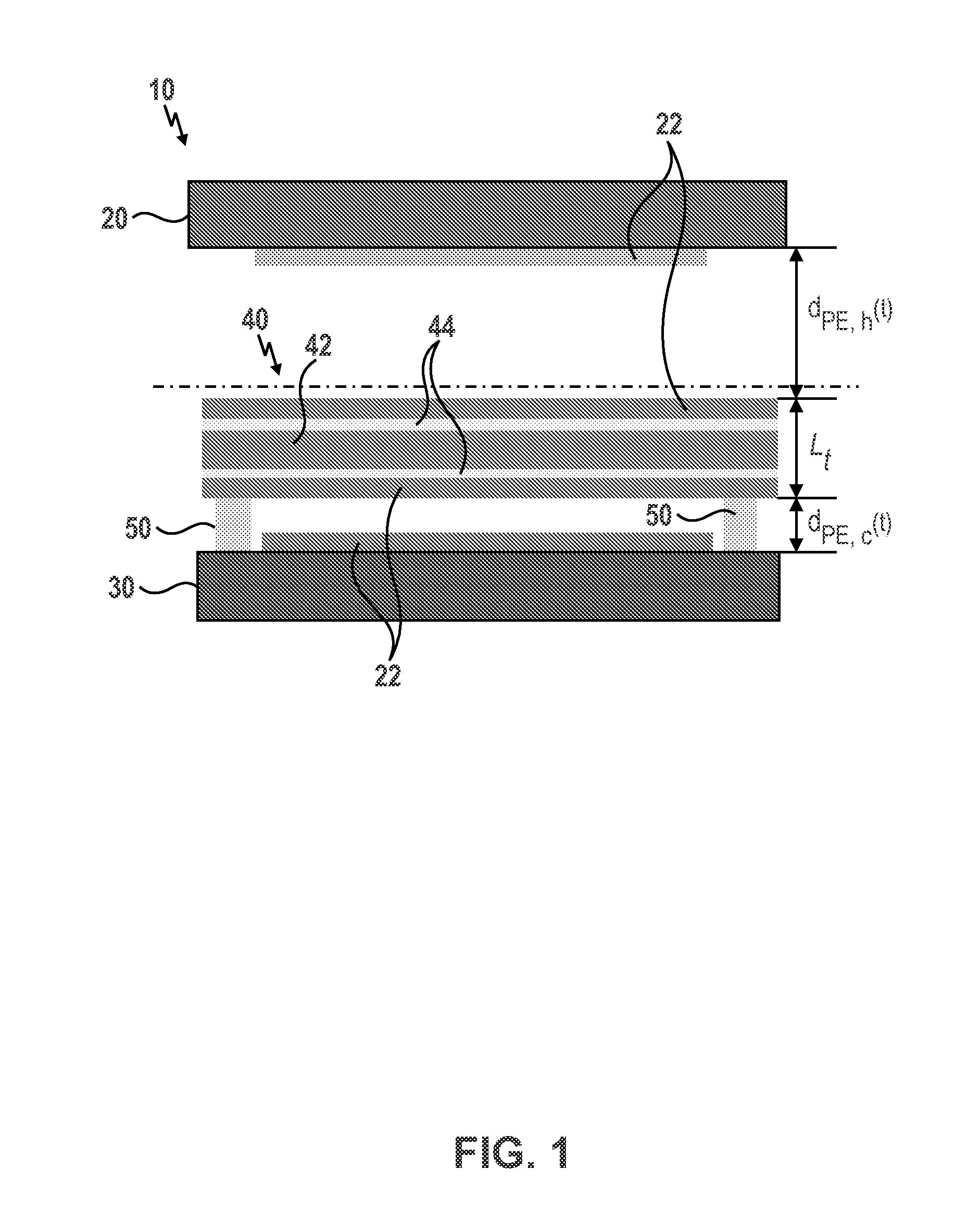
[0013]In another embodiment, the PE plate oscillates between the hot plate and the cold plate wherein the PE plate is alternatively brought in thermal contact with either the hot plate or the cold plate. Both sides of the PE plate and the inner surfaces of the hot plate and the cold plate can be treated to minimize the thermal contact resistance between them.
[0014]In one embodiment, silicon dioxide (SiO2) thin films of thickness LSiO<sub2>2< / sub2>, which act as absorbing layers capable of emitting and absorbing nanoscale radiation to enhance the radiative heat flux between the hot plate and the cold plate, can be coated on both sides of the PE plate and on the inner surfaces of the hot plate and the cold plate.
[0015]The PE plate can also be mounted on actuators, which allow the PE plate to oscillate between the hot plate and the cold plate. In one embodiment, the actuators may be configured to piezoelectric pillars. In operation, the converter can be operated under vacuum to minimize both friction on the oscillating PE plate and heat losses to the surroundings.

Problems solved by technology

Industrial and developing nations are facing challenges of meeting the rapidly expanding energy needs without further impacting the climate and the environment.
However, a significant amount of energy resource consumption is lost in the form of waste heat released as a by-product of power, refrigeration, or heat pump cycles.
Most of the lost energy appears as low grade waste heat which is hard to reuse because of its low temperature.
However, the converse is not true.
It is understood that this phase transition process from ferroelectric to paraelectric results in a large charge release.
Unfortunately, however, this process is highly irreversible, and theoretical analysis on such a PE energy conversion system predicts a low efficiency and a small power density.
Moreover, the operating frequency of such a conventional PE energy converter devices is usually small (˜0.1 Hz) and limited by convective heat transfer between the PE material and the working fluid subjected to oscillatory laminar flow between a hot and a cold source.
In turn, this restricts the performance of the device.

Method used


Image

  • Direct conversion of nanoscale thermal radiation to electrical energy using pyroelectric materials
  • Direct conversion of nanoscale thermal radiation to electrical energy using pyroelectric materials
  • Direct conversion of nanoscale thermal radiation to electrical energy using pyroelectric materials

Examples


Embodiment Construction

terial film made of 60 / 40 P(VDF-TrFE) with SiO2 absorbing layers as a function of frequency where the cold plate is held at Tc=273 K and the hot plate is held at Th=388 K.

[0029]FIG. 12 illustrates the maximum and minimum temperatures of oscillation of the PE plate comprising the PE material film made of 0.9 lead magnesium niobate-lead titanate (0.9 PMN-PT) with SiO2 absorbing layers as a function of frequency where the cold plate is held at Tc=283 K and the hot plate is held at Th=383 K.

[0030]FIG. 13 illustrates the efficiency ratios η / ηCarnot and η / ηCA as a function of frequency for one embodiment of the PE plate comprising the PE material film made of a single 60 / 40 P(VDF-TrFE) film and another embodiment of the PE plate comprising multiple PE material films made of 0.9PMN-PT.

DETAILED DESCRIPTION

[0031]Described herein is a pyroelectric energy converter 10 for use in the direct conversion of nanoscale thermal radiation to electrical energy using pyroelectric materials. The converte...


PUM


Abstract

The embodiment provided herein are directed to a pyroelectric (PE) energy converter which is capable of combining nanoscale thermal radiation and pyroelectric energy conversion for harvesting low grade waste heat. The converter advantageously makes use of the enhanced radiative heat transfer across a nanosize gap to achieve high operating frequencies or large temperature oscillations in a composite PE plate. The PE energy converter generally comprises a hot source, a cold source, and a PE plate, wherein the PE plate oscillates between the hot and cold source and the PE plate can be subjected to a power cycle in the displacement-electric field diagram. The hot and cold sources of the converter can be coated with SiO2 absorbing layer to further enhance the radiative heat fluxes. The converter comprising a PE plate made of 60 / 40 P(VDF-TrFE) operated between 273 K and 388 K experiences a maximum efficiency of 0.2% and a power density of 0.84 mW / cm2. The converter comprising a PE plate made of 0.9PMN-PT composite thin films achieve a higher efficiency and a larger power output namely 1.3% and 6.5 mW / cm2, respectively, for a temperature oscillation amplitude of 10 K around 343 K at 5 Hz.

Description

CROSS-REFERENCE TO RELATED APPLICATIONS[0001]This application claims the benefit of provisional application Ser. No. 61 / 352,284, filed Jun. 7, 2010, which is fully incorporated herein by reference.FIELD[0002]The present disclosure relates generally to pyroelectric energy converters, and more particularly to a direct conversion of nanoscale thermal radiation to electrical energy using pyroelectric materials.BACKGROUND INFORMATION[0003]Industrial and developing nations are facing challenges of meeting the rapidly expanding energy needs without further impacting the climate and the environment. However, a significant amount of energy resource consumption is lost in the form of waste heat released as a by-product of power, refrigeration, or heat pump cycles. Most of the lost energy appears as low grade waste heat which is hard to reuse because of its low temperature.[0004]Pyroelectric (PE) energy converters offer a direct energy conversion technology by transforming waste heat directly ...

Claims


Application Information

Patent Timeline
IPC IPC(8): H02N11/00
CPCH01L37/02H10N15/10
Inventor PILON, LAURENT G.
Owner RGT UNIV OF CALIFORNIA
Why Eureka
Eureka Blog
Learn More