
Canister flush valve

a technology of flush valve and canister valve, which is applied in the direction of valve member-seat contact, mechanical equipment, functional valve types, etc., can solve the problems of bowl overflow, water draining from the tank, and bowl overflow, so as to improve the control of the valve closure time and reduce leakage

Active Publication Date: 2007-05-10
KOHLER CO
View PDF29 Cites 15 Cited by
  • Summary
  • Abstract
  • Description
  • Claims
  • Application Information

AI Technical Summary

Benefits of technology

[0016] The present invention is an improved canister-type flush valve for a toilet that addresses the shortcomings of the prior art discussed above. Generally, the canister flush valve has a float and seal arrangement that can be raised by a trip lever from a valve body leading to or defining the tank outlet to unseat the seal, which normally seals off the tank outlet. The float / seal interface is configured to reduce leakage between the float and seal, and seating of the seal is assisted by direct application of water pressure head in the tank. The float is also configured to improve the control of the valve closure time.
[0017] In one aspect, the invention provides a canister flush valve having a valve body defining a valve seat and a flow passage leading from the valve seat toward an outlet when installed in a toilet tank. The flush valve has a float mounting a seal on a hollow longitudinally extending body with an open upper end a closed lower end. When installed in the tank, the open upper end extends above a water fill height of the tank to be in communication with ambient air, and the bottom wall at a lower end is below the water fill line. The bottom wall at least acts to restrict flow of water into the hollow body of the float during a flush cycle such that the hollow body can be suspending above the valve seat at least temporarily during the flush cycle by a buoyancy force of the water acting on an outside of the hollow body. Before and after a flush cycle the float is positioned to seat the seal on the valve seat and close off communication of tank water outside of the float with the flow passage. During a flush cycle, the float can be moved with respect to the valve body to unseat the seal and allow water within the tank to pass into the flow passage and out to the bowl.

Problems solved by technology

The bulbous stoppers of flapper valves are generally initially good at achieving and holding a seal, but over time (e.g. years of operation) may permit leakage.
Washer-like seals common in canister valves often have similar problems.
If the seal leaks, water will drain from the tank to the bowl.
This will cause the bowl to overflow, or if the bowl has overflow passages, water will pass from the bowl to the building plumbing lines.
Water is wasted in either case, which is very undesirable particularly given the emphasis local communities often place on the need for low water consumption toilets.
Sealing problems with conventional canister flush valves, arise from various factors.
While this is important, an often overlooked leak path arises at the float / seal interface.
Particularly over time with material shrinkage or degradation of the seal, water may leak through the space between the seal and the float.
This can become a low resistance leak path for water in the tank because the interface is typically a short, straight vertical path.
Existing canister flush valves fail in one or more of these areas, and thus provide a less than optimal seal.
Water consumption is largely a factor of the amount of time in which the flush valve is open.
One problem, however, with the use of bleed holes is that immediately after the float is moved, the pressure head in the tank is relatively high such that water will rush into the bleed holes quickly.
This is disadvantageous for several reasons, but primarily because of the possibility of the water spraying out the tank, or leaking down around on the rim of the tank, and onto the bathroom floor.

Method used


Image

  • Canister flush valve
  • Canister flush valve
  • Canister flush valve

Examples


Embodiment Construction

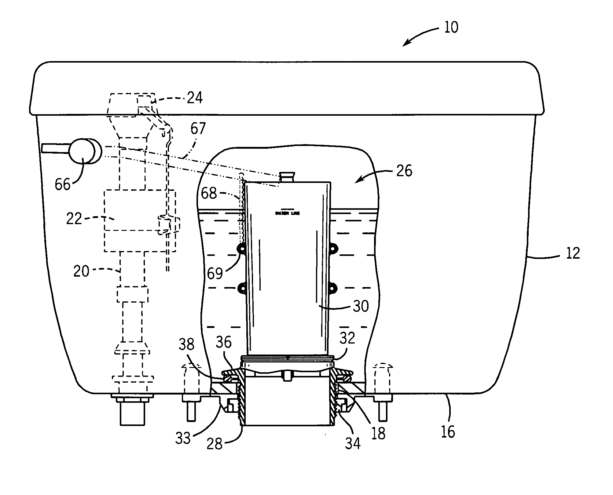
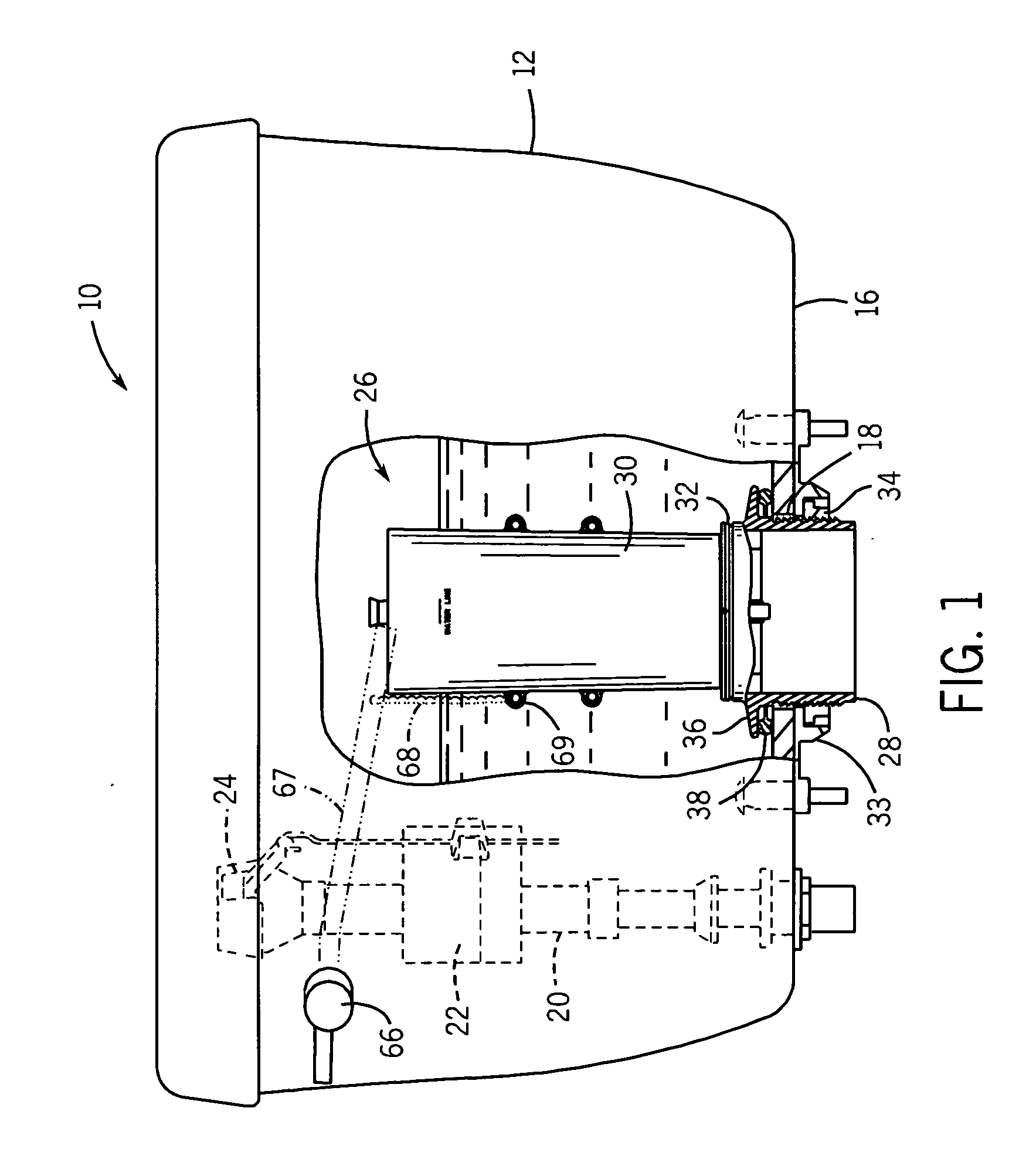
[0039] Referring now to the drawings, FIG. 1 shows a toilet 10 which includes a water tank 12 and a bowl section (not shown). The tank 12 has a horizontal bottom wall 16 with an outlet opening 18, which leads to a channel in an upper rim of the bowl. Mounted inside the tank is the usual water supply pipe 20 with a float 22 operated supply valve 24 for controlling the flow of supply water into the tank 12. A flush valve assembly 26 is mounted inside the tank 12 over the outlet opening 18 to control the flow of water from the tank 12 to the bowl during a flush cycle.

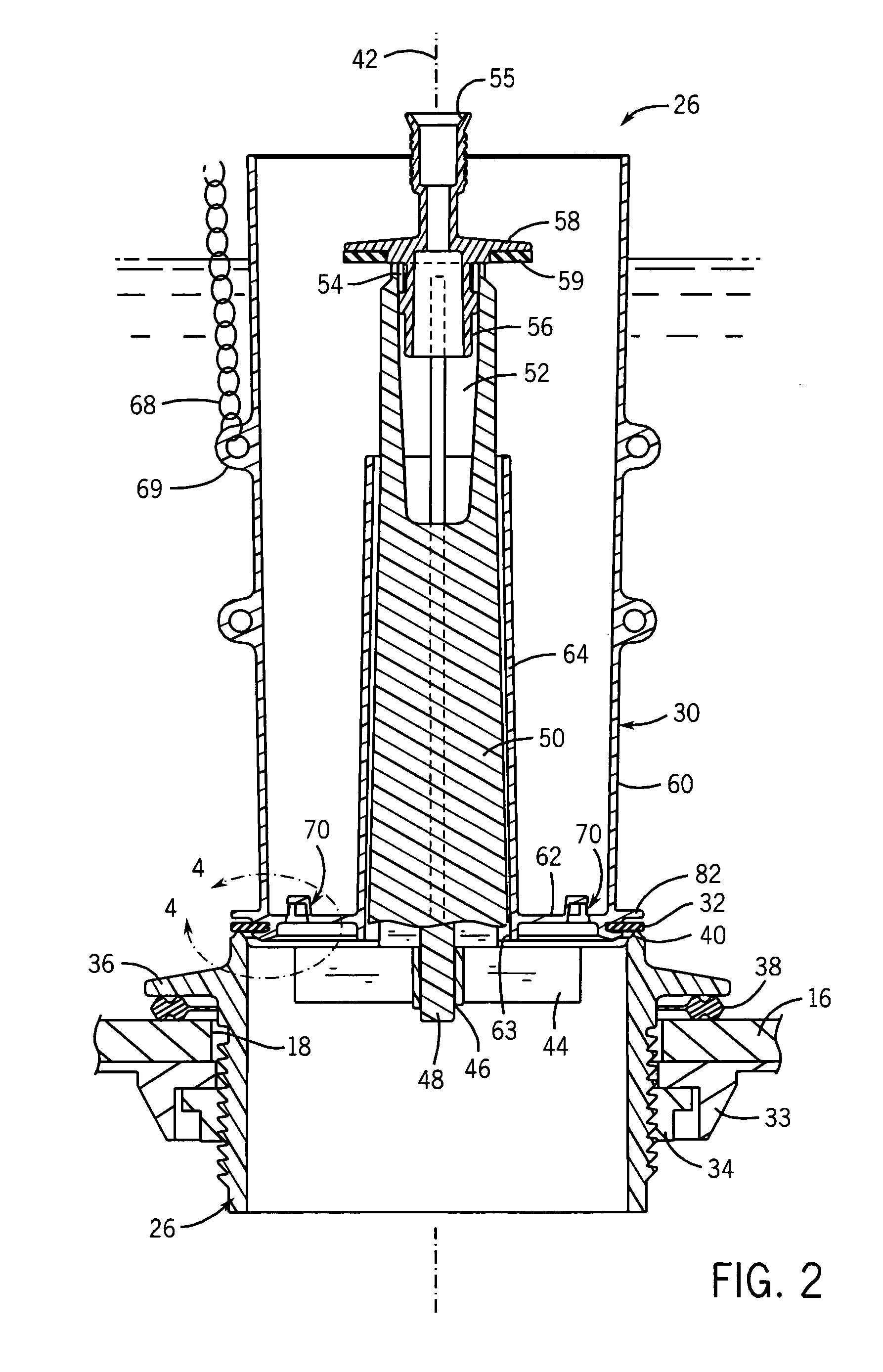
[0040] Referring to FIGS. 1, 2 and 6, the flush valve assembly 26 is mounted vertically upright in the tank 12 and primarily includes a valve body 28, a float 30 and a seal 32. The valve body 28 and float 30 are preferably a non-corrosive material, such as a suitable plastic. The seal can be made of a flexible material, for example a suitable elastomer, such as vinyl, EPDM rubber, or silicon, which has particularly good c...


PUM


Abstract

A canister type flush valve has an upright cup-shaped hollow float working under buoyancy forces without a captured air volume that controls the valve during a flush cycle. Hooded bleed openings at a bottom wall of the float can be sized and numbered to selectively control the closuring timing of the valve. Baffles of the hood bleed openings redirect water bleeding into the float to prevent the water from spraying up against the top of the tank. The geometry of a seal retaining groove is designed to reduce leakage at the float / seal interface. For example, the groove has an annular wall with a compound profile forming a non-cylindrical, preferably serpentine, seal contact area. The seal is backed by a slotted flange located just above the retaining groove.

Description

STATEMENT OF FEDERALLY SPONSORED RESEARCH OR DEVELOPMENT [0001] Not applicable.CROSS-REFERENCE TO RELATED APPLICATIONS [0002] Not applicable. BACKGROUND OF THE INVENTION [0003] The present invention relates to flush valves that control the flow of water from toilet tanks to toilet bowls. More particularly it relates to canister flush valves. [0004] Many systems for controlling the flush of toilet tank water to a toilet bowl are known, see e.g. U.S. Pat. Nos. 5,329,647 and 5,896,593. Such systems have a water inlet valve for the tank that is typically controlled by a float that senses tank water level. Depressing the trip lever moves a flush valve at the tank outlet so that water can empty from the tank through a vitreous pathway and into the bowl. As the tank water drains, the inlet valve float drops with the water level in the tank, thereby triggering inlet water flow. After sufficient tank water is drained, the flush valve closes so that the water level in the tank can be re-estab...

Claims


Application Information

Patent Timeline
Patent Type & Authority Applications(United States)
IPC IPC(8): E03D1/34
CPCE03D1/33E03D1/35F16K1/36F16K21/16F16K25/00
Inventor DENZIN, PETER W.
Owner KOHLER CO
Learn More