Fuel cell

a fuel cell and polymer electrolyte technology, applied in the field of fuel cells, can solve the problems of increasing pressure loss in the passage, unresolved problems, and the conventional separator designed for comparatively low working temperature will pose serious problems, so as to reduce the mechanical stress of the mea, reduce the blower loss, and reduce the effect of pressure loss

Inactive Publication Date: 2007-04-19
HITACHI LTD
View PDF2 Cites 16 Cited by
  • Summary
  • Abstract
  • Description
  • Claims
  • Application Information

AI Technical Summary

Benefits of technology

[0015] In the case of using a PEFC working at high temperatures, a new type separator is required having a structure different from the conventional type separator for a PEFC working at low temperatures. The present invention is to provide a new type separator capable of decreasing the pressure loss in the vicinity of its outlet and thereby of decreasing the blower loss the fuel cell. The present invention also is to provide an anode/cathode separator structure capable of decreasing the mechanical stress to the MEA, thereby of extending its life.
[0016] The present invention provides a fuel cell with a cathode separator for a PEFC working at 100° C. or higher, by increasing the sectional area of each passage with going downstream in the cathode separator. That is, the PEFC has the cathode separator w

Problems solved by technology

However, this problem is not solved by merely reducing the sectional area of the groove because more water occurs as available electric current increases.
In other words, the conventional separator designed for comparatively low working temperatures will pose serious problems if used for a PEFC working at high temperatures.
The following problem occurs when the conventional separator for a PEFC working at 70° C. is used for a PEFC working at 100° C. or higher.
In this situation, if the conventional passage structure provided for 70° C. is adopted in the separator of the PEFC, the pressure of the mixture in each passage of the separator increases as the mixture goes to the exist of the passage,

Method used


Image

  • Fuel cell
  • Fuel cell
  • Fuel cell

Examples


embodiment 1

[0050] This embodiment demonstrates an MEA capable of working at 100° C. or higher. The MEA has a composite electrolyte composed of S-PES (sulfonated polyether sulfone) as an organic polymer and zirconium oxide hydrate ZrO2·nH2O (as a moisture retention inorganic material) dispersed therein. The S-PES has an ion exchange capacity of 1.3 meq / g on dry basis. The zirconium oxide hydrate ZrO2·nH2O was derived from zirconium oxychloride ZrOCl2·8H2O as a precursor. A first varnish of ZrOCl2·8H2O (30 wt % in concentration) dissolved in dimethylsulfoxide was prepared. A second varnish of S-PES (30 wt % in concentration) dissolved in dimethylsulfoxide was prepared. The two vanishes were mixed with stirring for 2 hours by using a stirrer. The resulting varnish mixture was applied onto a glass plate by using an applicator, followed by vacuum drying at 80° C. for 1 hour and at 120° C. for 3 hours for evaporation of dimethylsulfoxide. The resulting film was peeled off from the glass plate and th...

embodiment 2

[0053] The same procedure as in Embodiment 1 was repeated to prepare the MEA suitable for working at 100° C. or higher.

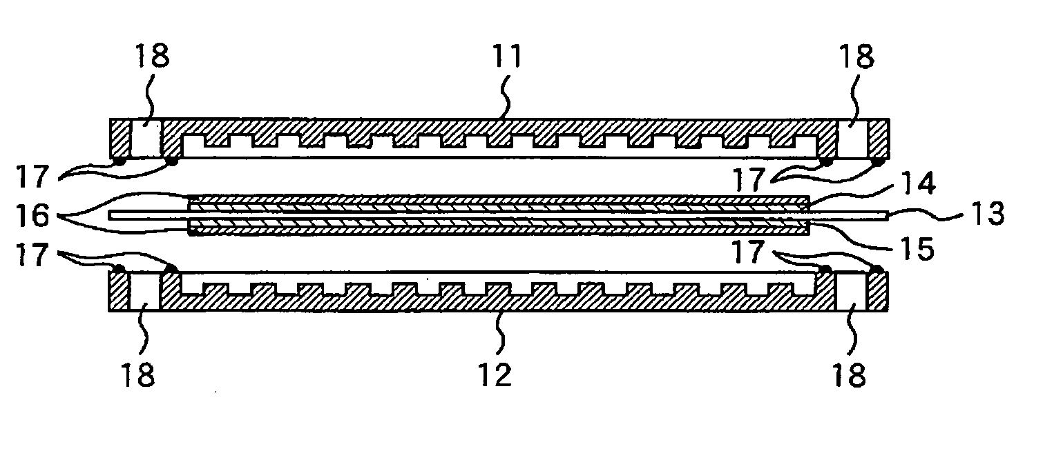
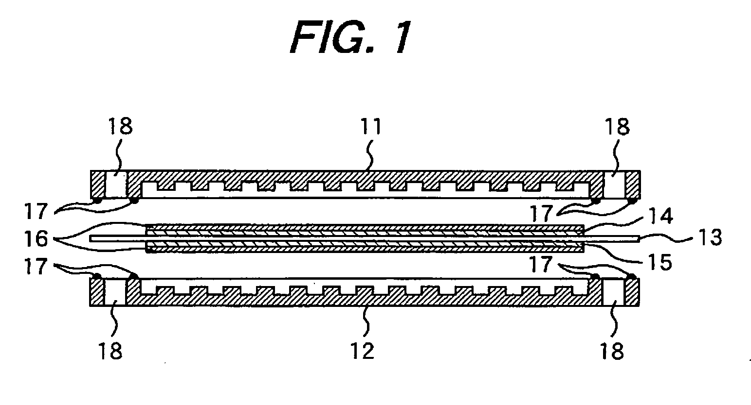
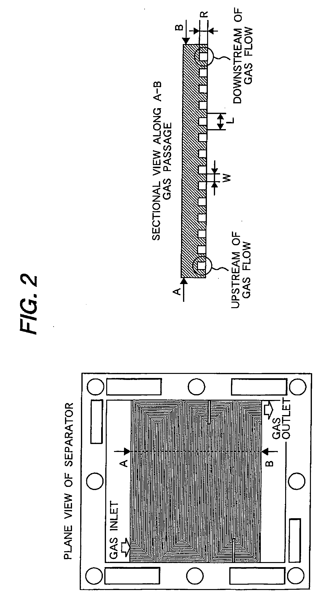
[0054] The resulting MEA was combined with the separators according to the present invention to make a single cell for testing. The separators were placed on both sides of the MEA, with PTFE-treated water-repellent carbon paper interposed between the MEA and the separator. All the components were fastened with bolts. The cathode separator according to the present invention has a rib pitch that increases with going downstream along the gas flow. For example, the rib pitch increases from 2.0 mm at the inlet to 6.0 mm at the outlet. The cathode separator also has a rib height of 1.0 mm and a rib width of 1.0 mm. The anode separator has a rib height of 1.0 mm, a rib width of 1.0 mm, and a rib pitch of 2.0 mm.

[0055] Test for power generation was performed under the same conditions as in Embodiment 1. During testing, the pressure at the inlet of the cathode separator wa...

embodiment 3

[0059] The same procedure as in Embodiment 1 was repeated to prepare the MEA suitable for working at 100° C. or higher.

[0060] The resulting MEA was combined with the separators according to the present invention to make a single cell for testing. The separators were placed on both sides of the MEA, with PTFE-treated water-repellent carbon paper interposed between the MEA and the separator. All the components were fastened with bolts. The cathode separator according to the Embodiment has a uniform rib pitch of 6.0 mm (at both the inlet and outlet). The cathode separator also has a rib height of 1.0 mm and a rib width of 1.0 mm. The anode separator has a uniform rib pitch of 2.0 mm at both the inlet and the outlet. It also has a rib height of 1.0 mm and a rib pitch of 1.0 mm.

[0061] The single cell was tested for life by measuring the variation in voltage with time, with the current density kept at 200 mA / cm2.


PUM


Abstract

A PEFC (polymer electrolyte fuel cell) has a cathode separator for a PEFC working at 100° C. or higher. The cathode separator has gas passages to fed oxidant gas. Each of the passages increases the sectional area thereof with going down stream along with gas flow. That is, the PEFC has the cathode separator whose passage is configured that the downstream side sectional area thereof is larger than the upstream side sectional area thereof. In addition, the area of contact between the rib surface of the anode separator and a diffusion layer of an anode is larger than the area of contact between the rib surface of the cathode separator and a diffusion layer of the cathode.

Description

CLAIM OF PRIORITY [0001] The present application claims priority from Japanese application serial no. 2005-302429, filed on Oct. 18, 2006, the content of which is hereby incorporated by reference into this application. FIELD OF THE INVENTION [0002] The present invention relates to a PEFC (polymer electrolyte fuel cell) being designed so as to work at high temperatures. BACKGROUND OF THE INVENTION [0003] A fuel cell is a device to convert chemical energy directly into electric energy. It is so designed as to generate electricity by electrochemical reaction using fuel (such as hydrogen and methanol) and oxidant gas (such as air). Fuel cells can be grouped as a solid polymer type, a phosphoric acid type, a molten carbonate type, a solid oxide type under sorts of electrolytes and working temperatures. The most promising of these fuel cells is PEFC (Polymer Electrolyte Fuel Cell). It is under active investigation because of its potential use as a household power supply and a mobile power...

Claims


Application Information

Patent Timeline
IPC IPC(8): H01M8/02H01M4/94
CPCH01M4/926H01M8/0206H01M8/026H01M8/04089H01M8/0612H01M2004/8689H01M2008/1095Y02E60/50H01M8/02
Inventor HIRASHIGE, TAKAYUKIYAMAGA, KENJI
Owner HITACHI LTD
Why Eureka
Try Eureka