
Process for protecting openings in a component during a treatment process, preventing penetration of material, and a ceramic material

a technology for ceramic materials and treatment processes, applied in the direction of resistive material coatings, machines/engines, group 4/14 element organic compounds, etc., can solve the problems of re-coating components, worms, and no longer being able to operate, and achieve the effect of increasing the content of ceramic materials

Inactive Publication Date: 2007-04-19
SIEMENS AG
View PDF6 Cites 15 Cited by
  • Summary
  • Abstract
  • Description
  • Claims
  • Application Information

AI Technical Summary

Benefits of technology

[0016] It is a further object of the present invention to provide a ceramic material which has advantageous properties and is particularly suitable for use in the process according to the invention.
[0022] The advantage of the process according to the invention over the previous processes is that the treatment process is not adversely affected to such an extent by the filling material. By way of example, during an MCrAlX coating process, what is known as cleaning sputtering takes place, in which the component is exposed to an arc. On account of the conductivity of the filling material being matched to the base material, the arc is not adversely affected to any significant extent at the transitions between the surface of the base material and the surface of the filling material. Any such adverse effect could lead to damage to the component. Many treatment processes, for example processes for coating the MCrAlX, also comprise at least one heating process. On account of the conductivity of the filling material being matched to the base material, the introduction of heat into the component is not disrupted at the transitions between the base material and the filling material.
[0025] The hardenable filling material can be introduced into at least some of the openings in particular in the form of a paste. The introduction of the paste, which can be effected for example by means of a spatula apparatus, offers the advantage that holes of any desired shape can be filled in this way.
[0027] Partially crosslinked filling bodies are filling bodies which comprise a polymer-based binder which has a partially crosslinked polymer architecture. A partially crosslinked state is also known as the “green state” and offers a higher dimensional stability compared to a paste, so that the material can maintain a physical form even prior to the hardening. Filling openings by means of partially crosslinked filling bodies of this type is especially suitable for introducing the filling material into large openings, as may occur for example in the region of the base of turbine blades or vanes. Moreover, it is also possible for the entire area of curved component surfaces to be protected by means of partially crosslinked filling bodies, for example if the partially crosslinked filling bodies are in the form of tapes or sheets.
[0033] The ceramic material may comprise a solvent for producing a dispersion of the binder and the filler. The use of the solvent makes it possible to form a ceramic material that is able to flow prior to being hardened, thereby allowing the material to be spread or sprayed into openings. Examples of suitable solvents include alcohol or terpeneol.
[0034] In an advantageous refinement of the ceramic material, the filler comprises particles in at least two particle sizes, the particle sizes in particular being in the nanometer range (in particular less than 0.1 μm) and / or the micrometer range. The filler content in the ceramic material can be increased by using particles of different sizes.

Problems solved by technology

During operation of the components, the coating or coatings become(s) worm, often before the structural integrity of the component has deteriorated to such an extent that it is no longer capable of operation.
However, it may also be necessary to recoat the components if the component is merely to be tested, for example for structural defects, specifically if all the coatings have to be removed in order to test the component.
During recoating, the problem arises that cooling-air bores are closed up or at least have their diameter reduced by the coating material, for example MCrAlX.
The reduction in the diameter in turn reduces the outlet area of the opening, thereby changing and possibly reducing the cooling action provided by the cooling film.
Moreover, if the outlet area of the opening becomes too small, the flow required for the cooling action, which is for example laminar or turbulent, may no longer be ensured.
In both cases, this leads to premature failure of the component as a result of overheating.
In this case, however, it is difficult to ensure that the masking material does not extend laterally beyond the edge of the hole, in order to ensure that after the recoating operation the coating does actually reach all the way to the edge of the hole.
Moreover, the polymers which are part of the filling material leave streaks of soot on the component when they are burnt out.

Method used


Image

  • Process for protecting openings in a component during a treatment process, preventing penetration of material, and a ceramic material
  • Process for protecting openings in a component during a treatment process, preventing penetration of material, and a ceramic material
  • Process for protecting openings in a component during a treatment process, preventing penetration of material, and a ceramic material

Examples


Embodiment Construction

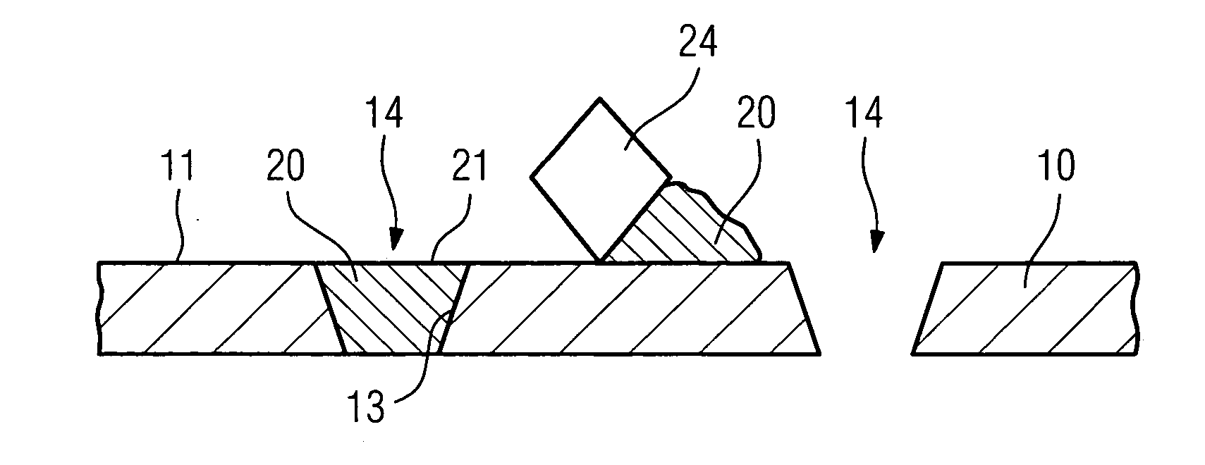
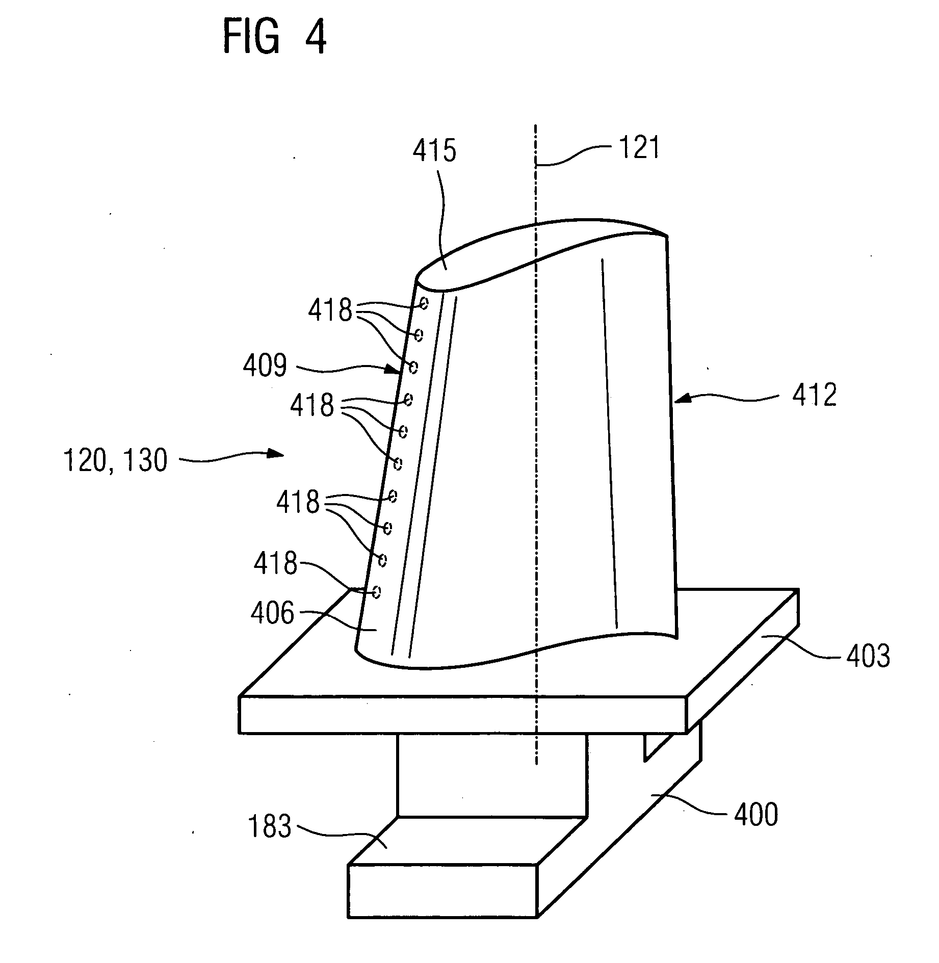
[0042]FIG. 1 diagrammatically depicts an excerpt from a turbine blade or vane 10, 120, 130 (FIGS. 4, 6). The following explanations also apply to other components which have holes, such as for example heat shield elements 155 (FIG. 5).

[0043] The turbine blade or vane 10 is joined to a baseplate 403 and has a number of cooling-air openings 14, of which in the present illustration only those which are located in the region of the leading edge 409 of the turbine blade or vane 10 are illustrated. Like the turbine blade or vane 10, the baseplate 403 has cooling-air openings 16, the diameter of which, in the present example, is larger than the diameter of the cooling-air openings 14 in the turbine blade or vane 10.

[0044] The cooling fluid, generally cooling air, is fed to the cooling-air openings 14 in the turbine blade or vane through cooling-air ducts, which are not illustrated and are arranged in the interior of the turbine blade or vane 10.

[0045] The turbine blade or vane 10 and th...


PUM

PropertyMeasurementUnit
particle sizesaaaaaaaaaa
electrically conductiveaaaaaaaaaa
electrical conductivityaaaaaaaaaa

Abstract

In the process according to the invention for protecting openings in a component made from an electrically conductive base material, in particular from metal or from a metal alloy, during a treatment process, preventing penetration of material, prior to the treatment process the openings are closed up using a filling material which is removed again following the treatment process. The process according to the invention is distinguished by the fact that chains of Si—O—Si and / or Si—O—C are used as filling material.

Description

CROSS REFERENCE TO RELATED APPLICATIONS [0001] This application claims the benefits of European Patent application No. 05021593.8 filed Oct. 4, 2005. All of the applications are incorporated by reference herein in their entirety. FIELD OF THE INVENTION [0002] The present invention relates to a process for protecting openings in a component during a treatment process to prevent penetration of material, in which prior to the treatment process the openings are closed up using a filling material. The invention also relates to a ceramic material, in particular for use as filling material in the process according to the invention. [0003] BACKGROUND OF THE INVENTION [0004] Components which are subject to high thermal stresses, for example turbine blades or vanes of gas turbines, are frequently covered with a cooling film for cooling purposes. For this purpose, these components comprise cooling-fluid ducts which are arranged in the interior and transport a cooling fluid used to build up the...

Claims


Application Information

Patent Timeline
Patent Type & Authority Applications(United States)
IPC IPC(8): C09D4/00B05D1/32
CPCC23C14/042F01D5/005Y02T50/67Y02T50/60
Inventor JABADO, RENEKORTVELYESSY, DANIELREICHE, RALPHRINDLER, MICHAELWALTER, STEFFEN
Owner SIEMENS AG
Learn More