
Integrated circuit solder bumping system

a solder bumping and integrated circuit technology, applied in the field of semiconductor technology, can solve the problems of metal and underlying polymer peeling cracking, requiring a longer deposition process time, and etching process also having problems

Active Publication Date: 2007-03-29
JCET SEMICON (SHAOXING) CO LTD
View PDF5 Cites 102 Cited by
  • Summary
  • Abstract
  • Description
  • Claims
  • Application Information

AI Technical Summary

Benefits of technology

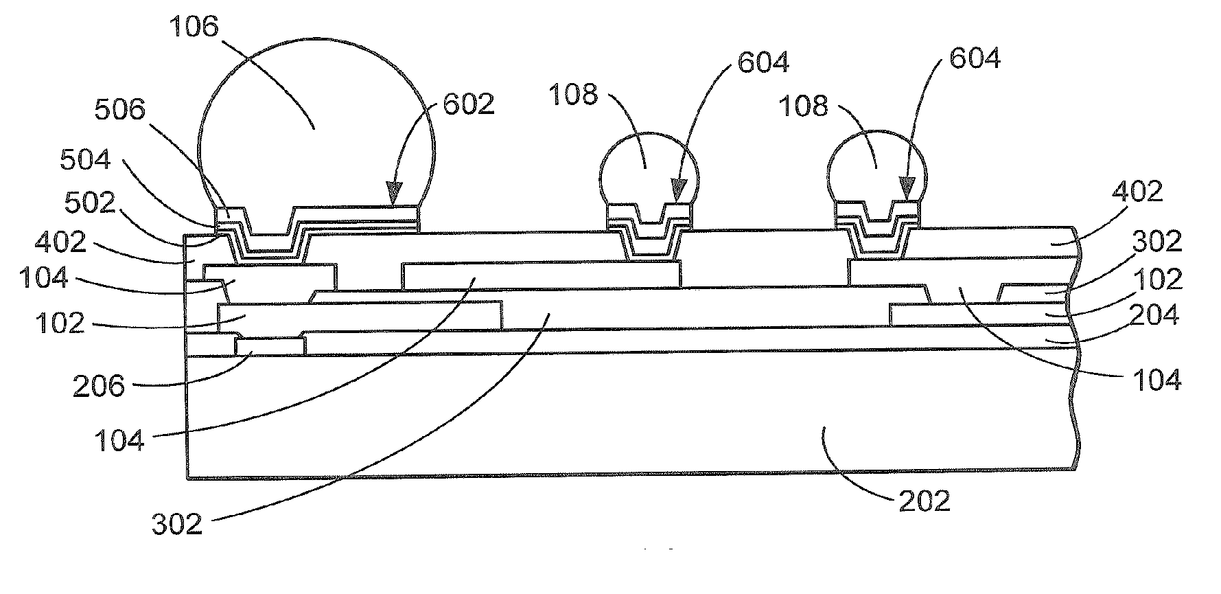
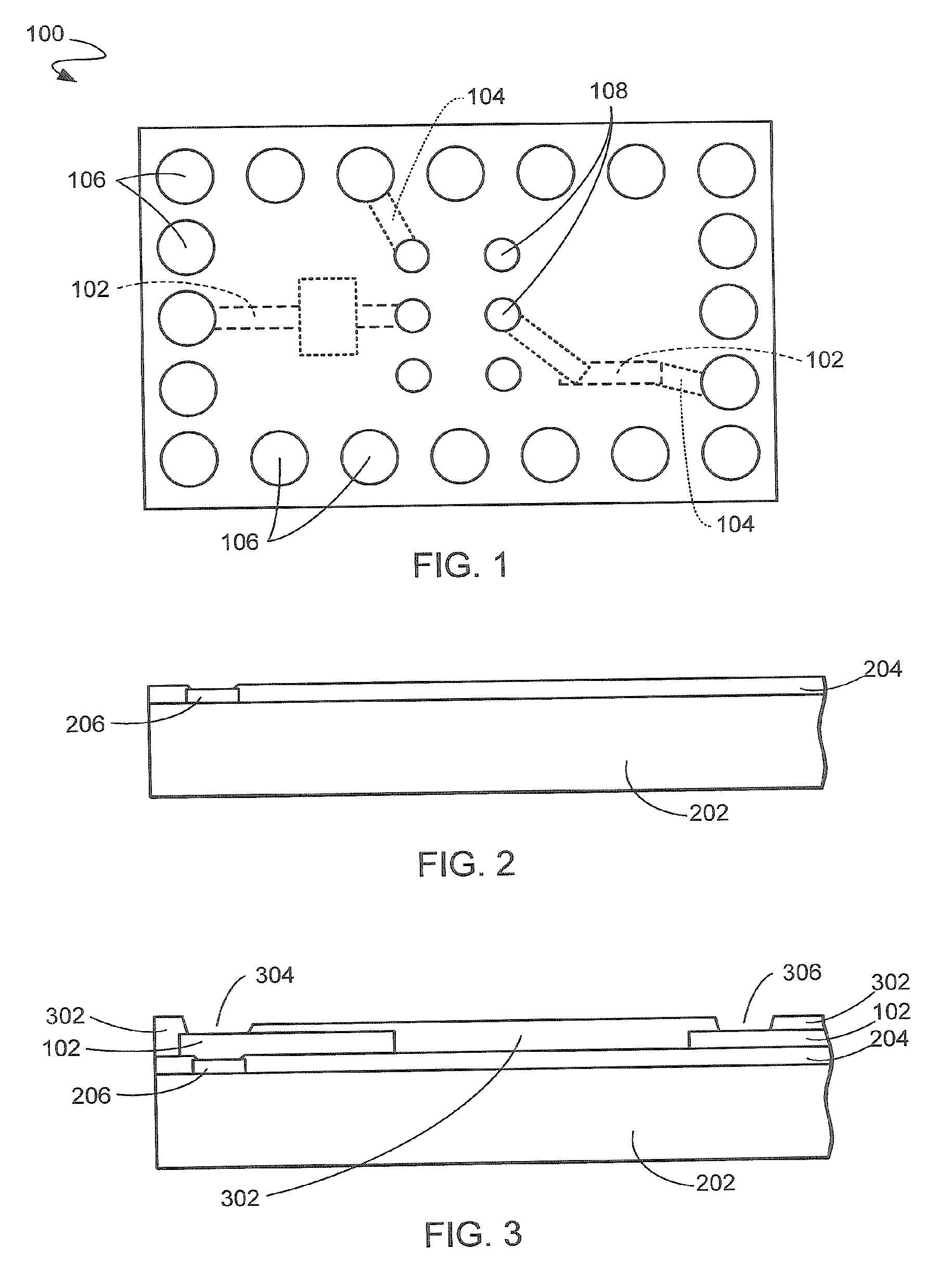
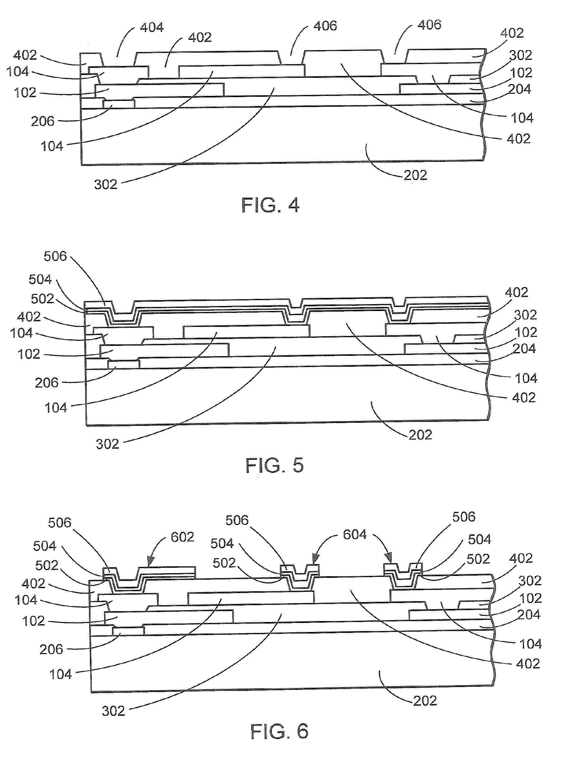
[0016] The present invention provides an integrated circuit solder bumping system. A substrate is provided and a redistribution layer is formed on the substrate. An insulation layer is formed on the redistribution layer. The insulation layer has a plurality of openings therethrough. A first UBM layer of titanium is deposited on the insulation layer and in the openings therethrough. A second UBM layer of chromium / copper alloy is deposited on the first UBM layer. A third UBM layer of copper is deposited on the second UBM layer. UBM pads of at least two different sizes are formed from the UBM layers. Solder paste is printed over at least some of the UBM pads. The solder paste is reflowed to form at least smaller solder bumps on at least some of the UBM pads. Bigger solder bumps are formed on at least some of the UBM pads.

Problems solved by technology

In addition, the shadow effect of the lift-off process requires a thicker metal deposition, therefore also requiring a longer deposition process time.
However, the etch-back process also has problems.
Otherwise, high residual stress may cause the metal and underlying polymer to peel and crack during patterning of the UBM pads for the etch-back process.
These defects may happen even earlier, just after the deposition of the UBM metal layers.
If the UBM structures of Ti / NiV / Cu and Cr / CrCu / Cu and the like are employed, the above defects are prone to happen.
Additional process steps can sometimes be taken to deter the defects from happening, but at the expense of reduced throughput and increased production cost.
In some applications, it may be possible to omit the barrier layer of NiV, but the barrier layer is needed under lead-free solder bumping because the large amount of tin (“Sn”) in the lead-free solder ball consumes the Cu intensively.
Another etch-back process problem has been encountered when a flip chip configuration has been adopted that utilizes both a peripheral array and a center area array at the same time for the flip chip interconnection.
However, in other cases, the bigger bumps and smaller bumps (e.g., having over 100°μm bump height difference) could not be formed on the substrate at the same time because of the technical limits of the photoresist thickness and the pitches between the UBM pads.
However, this caused production throughput to be reduced, and therefore, cost was increased.
Solutions to these problems have been long sought but prior developments have not taught or suggested any solutions and, thus, solutions to these problems have long eluded those skilled in the art.

Method used


Image

  • Integrated circuit solder bumping system
  • Integrated circuit solder bumping system
  • Integrated circuit solder bumping system

Examples


Embodiment Construction

[0031] The following embodiments are described in sufficient detail to enable those skilled in the art to make and use the invention, and it is to be understood that other embodiments would be evident based on the present disclosure and that process or mechanical changes may be made without departing from the scope of the present invention.

[0032] In the following description, numerous specific details are given to provide a thorough understanding of the invention. However, it will be apparent that the invention may be practiced without these specific details. In order to avoid obscuring the present invention, some well-known system configurations and process steps are not disclosed in detail. Likewise, the drawings showing embodiments of the invention are semi-diagrammatic and not to scale and, particularly, some of the dimensions are for the clarity of presentation and are shown exaggerated in the drawing FIGs. Also, where multiple embodiments are disclosed and described having so...


PUM

PropertyMeasurementUnit
thicknessaaaaaaaaaa
heightaaaaaaaaaa
temperaturesaaaaaaaaaa

Abstract

An integrated circuit solder bumping system provides a substrate and forms a redistribution layer on the substrate. An insulation layer is formed on the redistribution layer. The insulation layer has a plurality of openings therethrough. A first UBM layer of titanium is deposited on the insulation layer and in the openings therethrough. A second UBM layer of chromium / copper alloy is deposited on the first UBM layer. A third UBM layer of copper is deposited on the second UBM layer. UBM pads of at least two different sizes are formed from the UBM layers. Solder paste is printed over at least some of the UBM pads. The solder paste is reflowed to form at least smaller solder bumps on at least some of the UBM pads. Bigger solder bumps are formed on at least some of the UBM pads.

Description

TECHNICAL FIELD [0001] The present invention relates generally to semiconductor technology, as well as generally to integrated circuit systems that may include multi-layer redistribution, and that may include flip chip interconnections with multi-size solder bumps. BACKGROUND ART [0002] In the manufacture and assembly of electronic devices, flip chip technology is increasingly popular as a high-density interconnection technique for mounting and electrically connecting semiconductor dies (or “chips”) on redistribution substrates. Interconnection substrates for these techniques include silicon, ceramic, and flexible plastic, as well as printed circuit boards. The flip chip technique presents solder pads (typically utilizing solder balls) on the surface of the substrate. [0003] Flip chip interconnections provide the shortest electrical connecting paths, and therefore the highest electrical performance and speed. Flip chip interconnections also accommodate the greatest number of chips a...

Claims


Application Information

Patent Timeline
Patent Type & Authority Applications(United States)
IPC IPC(8): H01L23/495H01L21/44
CPCH01L24/11H01L2224/0231H01L2224/0401H01L2224/0603H01L2224/1132H01L2224/1147H01L2224/131H01L2224/1403H01L2924/01013H01L2924/01014H01L2924/01022H01L2924/01028H01L2924/01029H01L2924/0105H01L2924/01073H01L2924/01079H01L2924/01082H01L2924/01322H01L2924/014H01L2924/04941H01L2924/04953H01L2924/05042H01L2924/09701H01L2924/14H01L2924/1433H01L2924/19041H01L2924/19042H01L2924/30107H01L2224/05027H01L24/03H01L24/05H01L24/06H01L24/13H01L24/14H01L2224/05166H01L2224/05171H01L2224/05647H01L2224/11334H01L2224/11849H01L2224/11903H01L2224/13027H01L2224/05572H01L2924/00013H01L2924/01006H01L2924/01023H01L2924/01024H01L2924/01033H01L2924/0002H01L2224/13099H01L2924/00014H01L2224/13599H01L2224/05599H01L2224/05099H01L2224/29099H01L2224/29599H01L2224/05552H01L2224/14104H01L2924/00012
Inventor LIN, YAOJIANDO, BYUNG TAIALVAREZ, ROMEO EMMANUEL P.
Owner JCET SEMICON (SHAOXING) CO LTD
Learn More