
Silver salt photothermographic dry imaging material

a technology of photothermographic and dry imaging, which is applied in the field of silver salt photothermographic dry imaging material, can solve the problems of deteriorating image lasting quality or raw stock stability, and achieve the effects of reducing fogging, superior raw stock stability, and high maximum density

Inactive Publication Date: 2007-03-08
KONICA MINOLTA MEDICAL & GRAPHICS INC
View PDF4 Cites 1 Cited by
  • Summary
  • Abstract
  • Description
  • Claims
  • Application Information

AI Technical Summary

Benefits of technology

[0278] To improve electrification properties of photothermographic imaging materials, metal oxides and / or conductive compounds such as conductive polymers may be incorporated into the constituent layer. These compounds may be incorporated into any layer and preferably into a sublayer, a backing layer, interlayer between the light sensitive layer and the sublayer. Conductive compounds described in U.S. Pat. No. 5,244,773, col. 14-20. Specifically, the surface protective layer of the backing layer side preferably contains conductive metal oxides, whereby advantageous effects of this invention (for example, tracking characteristics in thermal development) were proved to be enhanced.
[0279] The conductive metal oxide is crystalline metal oxide particles, and one which contains oxygen defects or one which contains a small amount of a heteroatom capable of forming a donor for the metal oxide, both exhibit enhanced conductivity and are preferred. The latter, which results in no fogging to a silver halide emulsion is preferred. Examples of metal oxide include ZnO, TiO2, SnO2, Al2O3, In2O3, SiO2, MgO, BaO, MoO3 and V2O5 and their combined oxides. Of these, ZnO, TiO2 and SnO2 are preferred. As an example of containing a heteroatom, addition of Al or In to ZnO, addition of Sb, Nb, P or a halogen element to SnO2, and addition of Nb or Ta to TiO2 are effective. The heteroatom is added preferably in an amount of 0.01 to 30 mol %, and more preferably 0.1 10 mol %. To improve particle dispersibility and transparency, a silicon compound may be added in the course of particle preparation.
[0280] The metal oxide particles have electric conductivity, exhibiting a volume resistance of 107 Ω·cm or less and preferably 105 Ω·cm or less. The foregoing metal oxide may be adhered to other crystalline metal oxide particles or fibrous material (such as titanium oxide), as described in JP-A Nos. 56-143431, 56-120519 and 58-62647 and JP-B No. 50-6235.
[0281] The particle size usable in this invention is preferably not more than 1 μm, and a particle size of not more than 0.5 μm results in enhanced stability after dispersion, rendering it easy to make use thereof. Employment of conductive particles of 0.3 μm or less enables to form a transparent photothermographic material. Needle-form or fibrous conductive metal oxide is preferably 30 μm or less in length and 1 μm or less in diameter, and more preferably 10 μm or less in length and 0.3 μm or less in diameter, in which the ratio of length to diameter is preferably 3 or more. SnO2 is also commercially available from Ishihara Sangyo Co., Ltd., including SNS10M, SN-100P, SN-100D and FSS10M.
[0282] The photothermographic material of this invention is provided with at least one image forming layer as a light-sensitive layer on the support. There may be provided an image forming layer alone on the support but it is preferred to form at least one light-insensitive layer on the image forming layer. For instance, a protective layer may be provided on the image forming layer to protect the image forming layer. Further, to prevent blocking between photothermographic materials or adhesion of the photothermographic material to a roll, a back-coat layer may be provided on the opposite side of the support.
[0283] A binder used in the protective layer or the back coat layer can be chosen preferably from polymers having a higher glass transition point (Tg) than a binder used in the image forming layer and exhibiting resistance to abrasion or deformation, for example, cellulose acetate, cellulose butyrate or cellulose propionate.

Problems solved by technology

However, the use of development accelerators produced problems such as deteriorated image lasting quality or raw stock stability.

Method used


Image

  • Silver salt photothermographic dry imaging material
  • Silver salt photothermographic dry imaging material
  • Silver salt photothermographic dry imaging material

Examples


example 1

Preparation of PET Support:

[0322] According to the conventional method, polyethylene terephthalate (PET) exhibiting an intrinsic viscosity (IV) of 0.66 (in phenol / tetrachloroethane=6 / 4 by weight) was obtained using terephthalic acid and ethylene glycol. After pelleting, the PET was dried over 4 hrs. at 130° C., melted at 300° C., extruded through a T-type die and subjected to rapid cooling to obtain unstretched film exhibiting a thickness of 175 μm after being having been subjected to heat-fixing.

[0323] The thus obtained film was longitudinally stretched by a factor of 3.3 using rolls differing in circumferential speed and laterally stretched 4.5 times using a tenter at temperatures of 110° C. and 130° C., respectively. The stretched film was subjected to heat-fixing at 240° C. for 20 sec. and then subjected to relaxation in the lateral direction at the same temperature. Thereafter, a portion corresponding to the chuck of the tenter was slit off and both edges were subjected to a...


PUM


Abstract

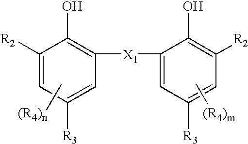
A silver salt photothermographic dry imaging material is disclosed, comprising on a support a light-sensitive layer comprising light-insensitive aliphatic carboxylic acid silver salt particles, light-sensitive silver halide grains, a binder and a reducing agent, wherein the reducing agent comprises a compound represented by the following formula and 80 to 100 mol % of total aliphatic carboxylic acid silver salts constituting the aliphatic carboxylic acid silver salt particles is accounted for by silver behenate.

Description

[0001] This application claims priority from Japanese Patent Application No. JP2005-254550 filed on Sep. 2, 2005, which is incorporated hereinto by reference. FIELD OF THE INVENTION [0002] The present invention relates to a silver salt photothermographic dry imaging material (hereinafter, also denoted simply as a photothermographic material) comprising on a support an organic silver salt, silver halide grains, a binder and a reducing agent, and an image forming method by use thereof. BACKGROUND OF THE INVENTION [0003] In the fields of medical diagnosis and graphic arts, there have been concerns in processing of photographic film with respect to effluent produced from wet-processing of image forming materials, and recently, reduction of the processing effluent has been strongly demanded in terms of environmental protection and space saving. Accordingly, thermally developable silver salt photothermographic dry imaging materials which can form images only upon heating were put into pra...

Claims


Application Information

Patent Timeline
IPC IPC(8): G03C1/00
CPCG03C1/385G03C1/498G03C1/49809G03C1/49818G03C1/49827G03C1/49863G03C1/74G03C1/32G03C2200/26G03C1/08G03C2001/03558G03C2001/03564G03C2001/03594
Inventor GOTO, NARITOOHNUMA, KENJI
Owner KONICA MINOLTA MEDICAL & GRAPHICS INC
Learn More