
Device and method for a combined interferometry and image-based determination of geometry, especially for use in micro system engineering

Active Publication Date: 2007-02-15
CARL MAHR HLDG
View PDF6 Cites 13 Cited by
  • Summary
  • Abstract
  • Description
  • Claims
  • Application Information

AI Technical Summary

Benefits of technology

[0008] The apparatus according to the invention comprises an object lens which can operate in at least two different measuring modes. In a first, interference mode a workpiece is measured by means of interference optometry. In a second, imaging measuring mode an optical image is produced, for example, on a camera-like detector array and may be applied to an image processing routine. Switching between the two measuring modes is performed by the type of illumination of the object lens and an element which is disposed preferably in the reference beam path of an interferometer and which activates or deactivates the reference beam path dependent on the spectral composition of the utilized light. In this manner a simple and rapid changeover between the two measuring modes is provided, without the need for replacing or even for moving the object lens. Apart from the rapidity of changeover, a good correlation is achieved between the measuring data which are yielded by the interferometry and by the image processing and which are obtained in one and the same reference coordinate system.
[0009] In the apparatus and the method according to the invention at least two measuring modes are available, that is, an interferometric measuring mode and an image processing mode with optical imaging of the workpiece. The changeover between the two measuring modes is effected by switching the light used for illuminating the workpiece. By light there are meant electromagnetic waves having a short wavelength. The apparatus according to the invention makes possible to provide a compact sensor module which has only a single object lens directed to the workpiece and with which interferometric measurements of vertically high resolution as well as image processing-based measurements of laterally high resolution may be performed. This is achieved by using, for the white light interferometric measurement, only one defined spectral light component to which the utilized camera is sensitive and by using another spectral component for the pure image processing. In the light microscopic measuring mode, for example, a blue LED (light emitting diode) may be active in the illuminating beam, and for the white light interferometry a white light LED may be provided. In the white light interferometric mode the blue LED is switched off and the white light LED is active. In this manner, with small outlay, a light microscopic measurement, as well as an interferometric measurement may be performed in the same reference system, in each instance with optimized accuracy. By virtue of light microscopic “scanning” with subsequent interferometric measurement, the possibility is further provided to obtain rapid automatic measuring processes. Furthermore, in the light microscopic measuring mode a rapid verification of the dynamic behavior of the examined workpiece or system may be performed.
[0012] By applying the approach to the Michelson object lens too, larger measuring ranges may be detected with one measuring process (at a reduced lateral resolution corresponding to the smaller numeric aperture). On the other hand, the Linnik arrangement is expedient for minimizing the lateral resolution, by selecting a possibly large numeric aperture for the object lens. It is further feasible to utilize several object lenses, for example, by means of an object lens turret provided in the apparatus.
[0015] The coupling of the measuring apparatus with the mechanical positioning units for the X, Y and Z axis which may be provided with suitable incremental measuring systems, allows to correlate measurements of different workpiece zones with one another. Dependent on the measuring task, rotational positioning axes too, may be expedient.
[0016] The apparatus according to the invention may be designed as a compact sensor module and makes possible a great number of applications at relatively small instrument costs, particularly in the field of micro system technology. It takes into account the continuously increasing requirements concerning the measuring accuracy and the process-oriented and flexible application possibilities. The use of LED's as light sources as opposed to the thermal beams used in the prior art white light interferometry has significant advantages as concerns freedom of configuration, compactness, life expectancy and reduction of thermal noise effects.

Problems solved by technology

All microscopic processes are, however, subject to limitations as concerns the attainable lateral resolution because of the deflection-limited imaging.
In case the evaluation of lateral structures base on digitalized light microscopic captures is to be performed by one of the above-noted interferometric arrangements, the interference effects necessarily appearing in the interference microscopy have an adverse effect because of the additional image contrasts conditioned thereon.
The exact correlation, however, between the height position determined with the white light interferometry and a light microscopic image captured with limited depth sharpness becomes lost.
A further drawback resides in the expenses of the additional object lens and an object lens turret which may be required for an automatic changeover between the two measuring modes.

Method used


Image

  • Device and method for a combined interferometry and image-based determination of geometry, especially for use in micro system engineering
  • Device and method for a combined interferometry and image-based determination of geometry, especially for use in micro system engineering
  • Device and method for a combined interferometry and image-based determination of geometry, especially for use in micro system engineering

Examples


Embodiment Construction

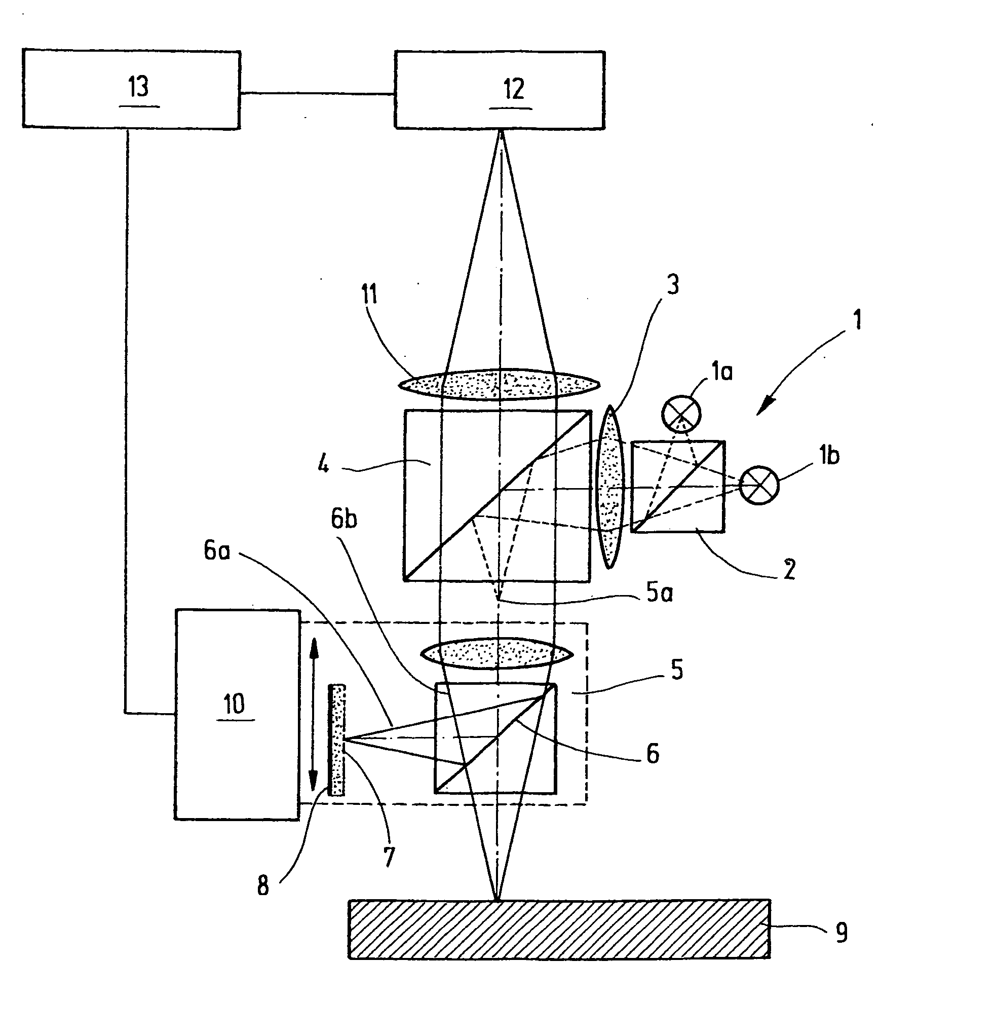
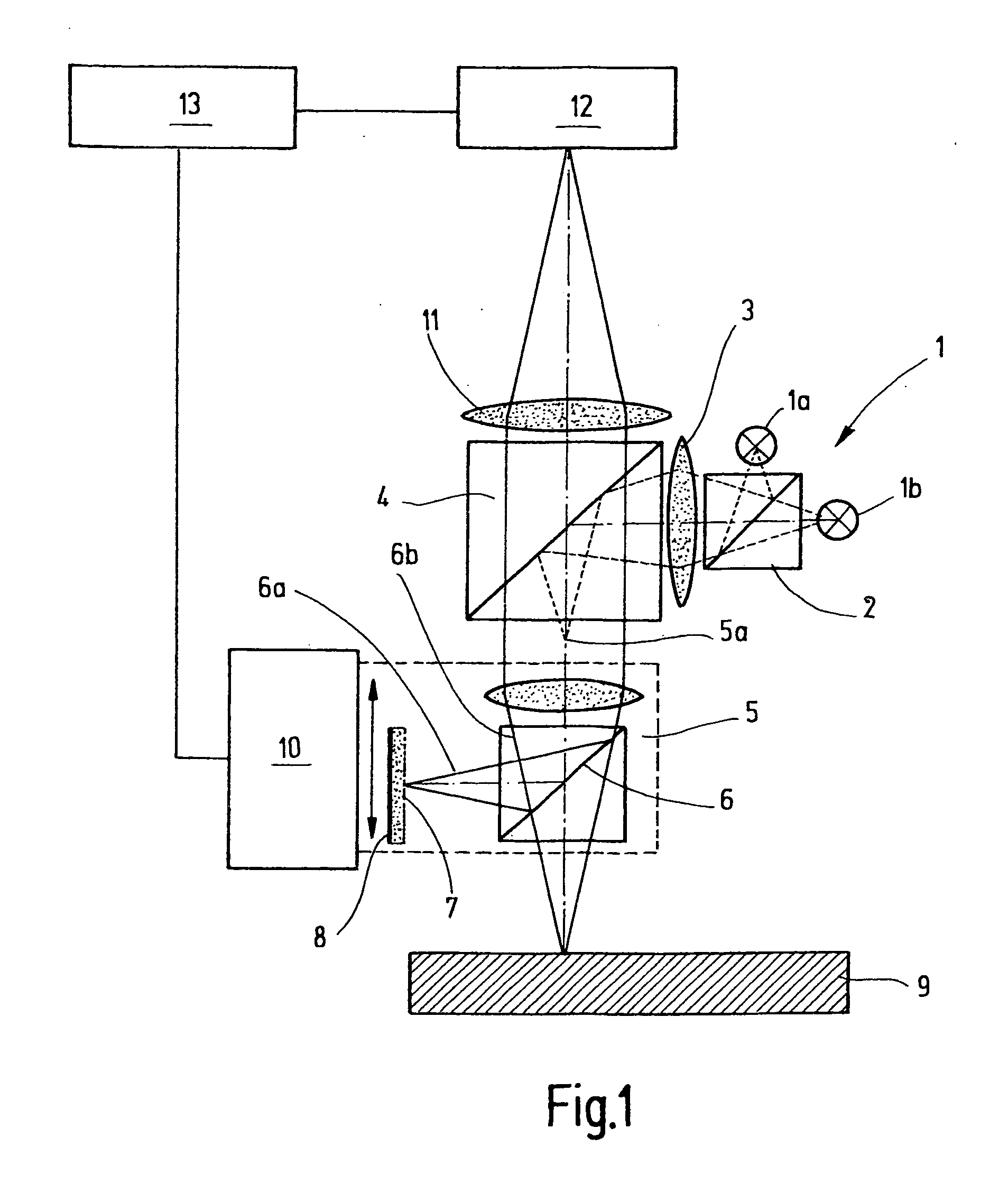
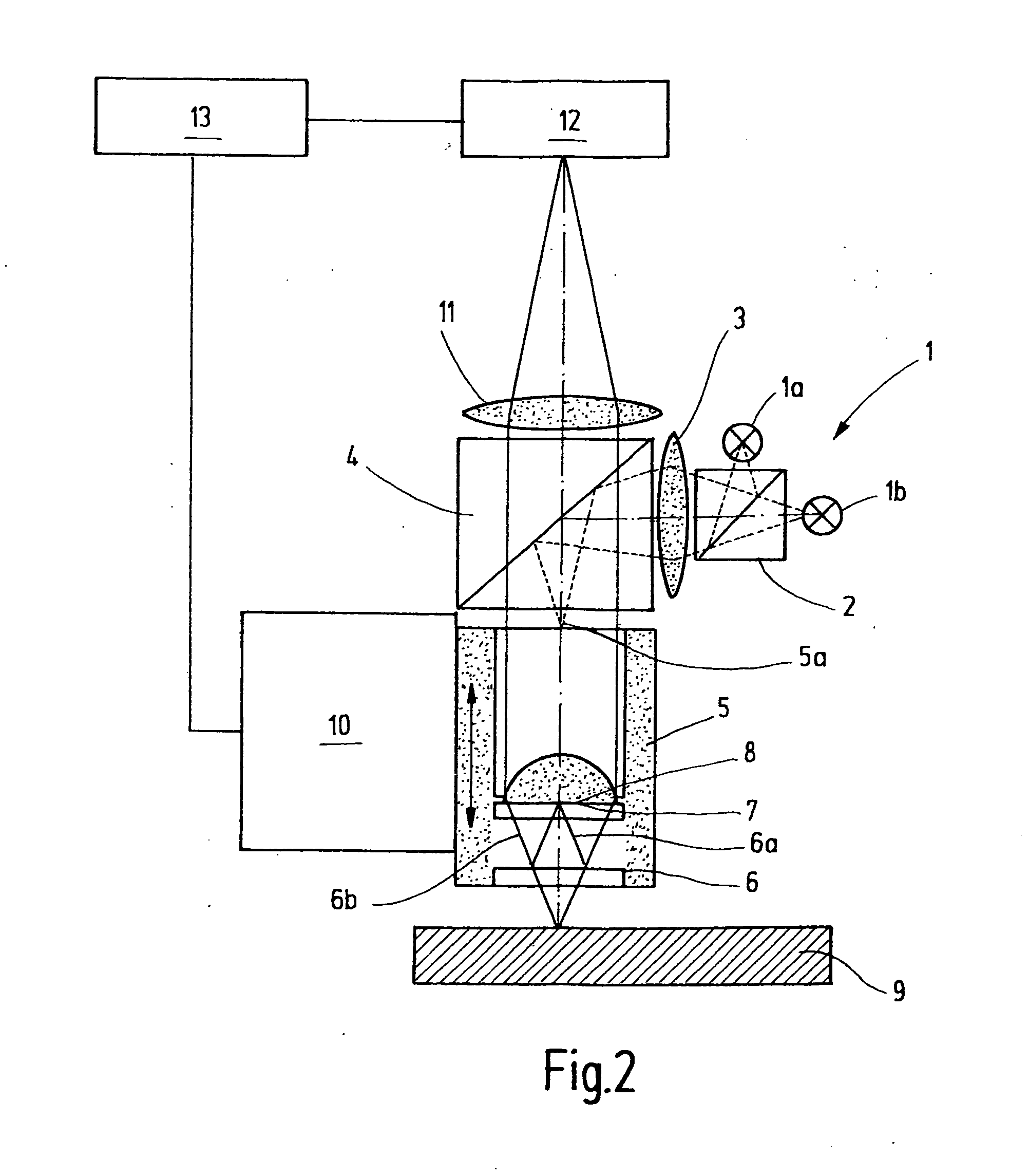
[0024]FIG. 1 illustrates an apparatus for a combined two-dimensional detection of height magnitudes of a workpiece 9, alternatively in an interferometric measuring mode and in an image processing mode by means of an optical imaging of the workpiece 9. The apparatus includes an arrangement for a reflecting light illumination of the workpiece 9. The apparatus comprises two light sources 1a, 1b with an optical system connected thereto for directing the light onto the workpiece. The light sources 1a, 1b emit light having different spectral compositions. For example, the light source 1a is a light emitting diode (LED) emitting blue light, that is, a short-wave beam. The light source 1b is, for example, a white light LED which generates a relatively wide light spectrum. The light sources 1a, 1b are reproduced, for example, by a dichroic beam splitter 2, a condenser 3 and a further beam splitter 4 on the inlet pupil 5a of an object lens 5, including an integrated beam splitter 6, a referen...


PUM


Abstract

The apparatus according to the invention comprises an object lens which can operate in at least two different measuring modes. In a first, interference mode a workpiece is measured by means of interference optometry. In a second, imaging measuring mode an optical image is produced, for example, on a camera-like detector array and may be applied to an image processing routine. Switching between the two measuring modes is performed by the type of illumination of the object lens and an element which is disposed preferably in the reference beam path of an interferometer and which activates or deactivates the reference beam path dependent on the spectral composition of the utilized light. In this manner a simple and rapid changeover between the two measuring modes is provided, without the need for replacing or even for moving the object lens. Apart from the rapidity of changeover, a good correlation is achieved between the measuring data which are yielded by the interferometry and by the image processing and which are obtained in one and the same reference coordinate system.

Description

CROSS-REFERENCE TO RELATED APPLICATION [0001] This is a continuation-in-part application of international application PCT / EP2005 / 004795 filed May 3, 2005, and claiming the priority of German application 10 2004 022 341.6 filed May 4, 2004.BACKGROUND OF THE INVENTION [0002] The invention relates to an apparatus and a method for a combined two-dimensional detection of height magnitudes of a workpiece. The apparatus and the method are adapted particularly for measuring tasks in the micro system technology. [0003] For optically measuring height structures with the greatest accuracy even in case of stepped workpieces, the vertically scanning white light interferometry (WLI) has been found to be adapted. The usual interferometric arrangements therefor are the Michelson interferometer, the Linnik interferometer and the Mirau interferometer. In the WLI a white light source, typically a halogen lamp is used for illumination. During measurement, the optical path length difference between the ...

Claims


Application Information

Patent Timeline
IPC IPC(8): G01B11/02G01B9/04G01B11/24
CPCG01B11/2441G01B9/04
Inventor LEHMANN, PETERSTEFFENS, NORBERT
Owner CARL MAHR HLDG
Learn More