
One-step scalable fabrication of mechanically robust visible-light responsive oxide-modified metallic multifunctional membranes

Active Publication Date: 2022-10-25
KING FAHD UNIVERSITY OF PETROLEUM AND MINERALS
View PDF7 Cites 0 Cited by
  • Summary
  • Abstract
  • Description
  • Claims
  • Application Information

AI Technical Summary

Benefits of technology

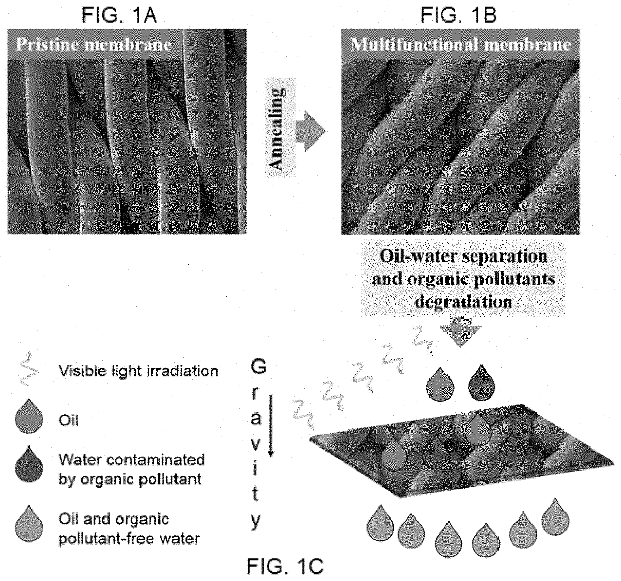
The patent describes a method for creating a stainless steel membrane with a smooth surface and good water affinity, which can repel oil and be used for industrial applications such as separating oil and water. The method is simple and cost-effective, and the membrane has good photocatalytic activity. It can be scaled up for large-scale use in wastewater treatment.

Problems solved by technology

The surface energy of the material is a necessary but not a sufficient factor to decide the wettability, as the surfaces with certain surface energies may not yield the expected contact angle.
The disadvantage of oil-passing membrane is that as the oil comes direct contact with the membrane surface, the surface easily gets fouled up and also as the density of water is higher than that of oil, water sneaks below the oil and forms a water layer and this prevents the efficient permeation of oil and hence limiting the efficiency of oil water separation; Kwon, G., Post, E.
In the second water passing kind of membranes, in order for a surface to be superhydrophilic-superoleophobic, the surface energy of the surface should be lower than that of oil and higher than that of water and hence realizing membranes of such wettability is quite difficult.
Despite high separation efficiency, anti-fouling property and low energy consumption during separation operation, it can be limited by inability to degrade the water-soluble organic pollutants present in the permeate (e.g., water-rich permeate).
While a few methods have been developed to fabricate under-water superoleophobic-photocatalytic textured multifunctional membranes, these methods typically involve expensive equipment, environmental hazards, or multi-step processes.
Furthermore, the wide band gap of most of these materials (>3.2 eV which is located in the UV region of the spectrum) limits the large-scale application of such material under solar light irradiation (i.e. UV spectrum is only 5% of the solar spectrum); see Mills, A.
However, these materials are typically used on substrate types that are not amenable to use in membrane separation applications that require at least partial submersion in a liquid.

Method used


Image

  • One-step scalable fabrication of mechanically robust visible-light responsive oxide-modified metallic multifunctional membranes
  • One-step scalable fabrication of mechanically robust visible-light responsive oxide-modified metallic multifunctional membranes
  • One-step scalable fabrication of mechanically robust visible-light responsive oxide-modified metallic multifunctional membranes

Examples


examples

[0057]Experimental Methods

[0058]The porous stainless steel membrane used to separate oil and water in this Example is a corrosion resistant annealed stainless steel (316L) square mesh of 3 cm sides, 1 mm thickness and 2 micron pore size.

[0059]Before annealing, the mesh was cleaned in an ultrasonic cleaner with deionized (“DI”) water and acetone and dried by nitrogen.

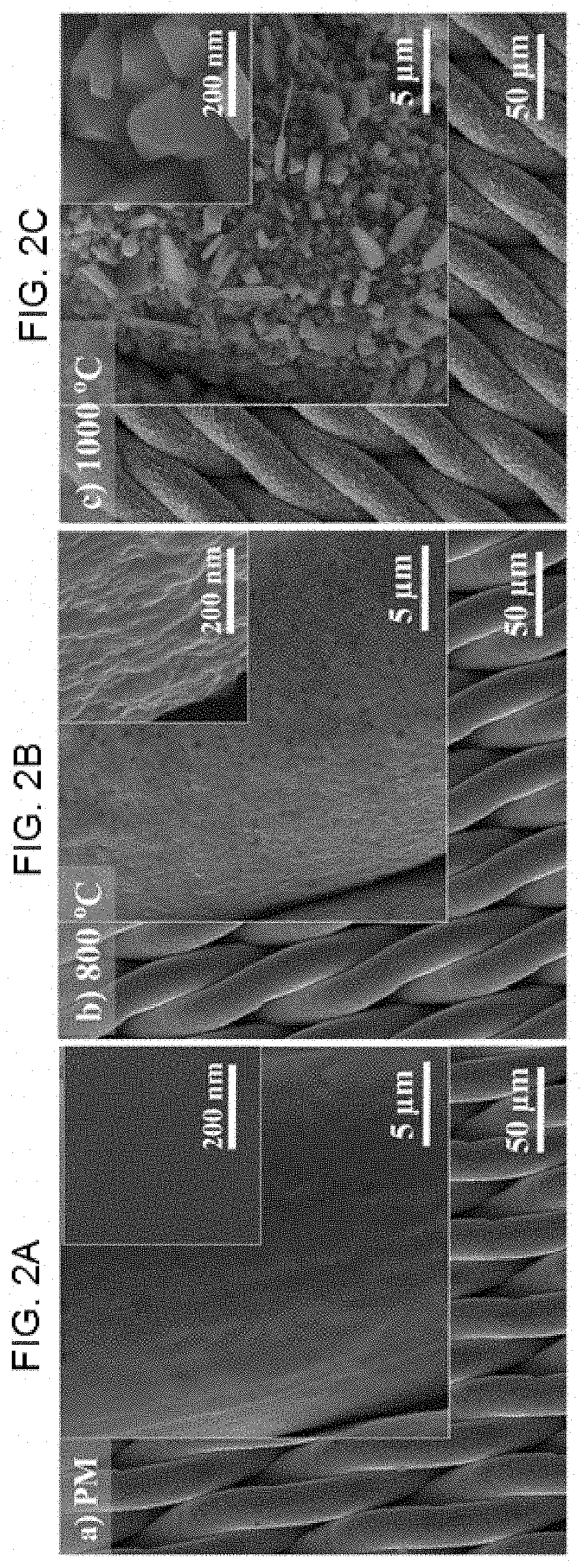
[0060]The stainless steel mesh was annealed at 1 atmospheric pressure in air and heated at 5° C. / min to a temperature of 800° C. or 1,000° C. an annealed at these temperatures for 3 hours.

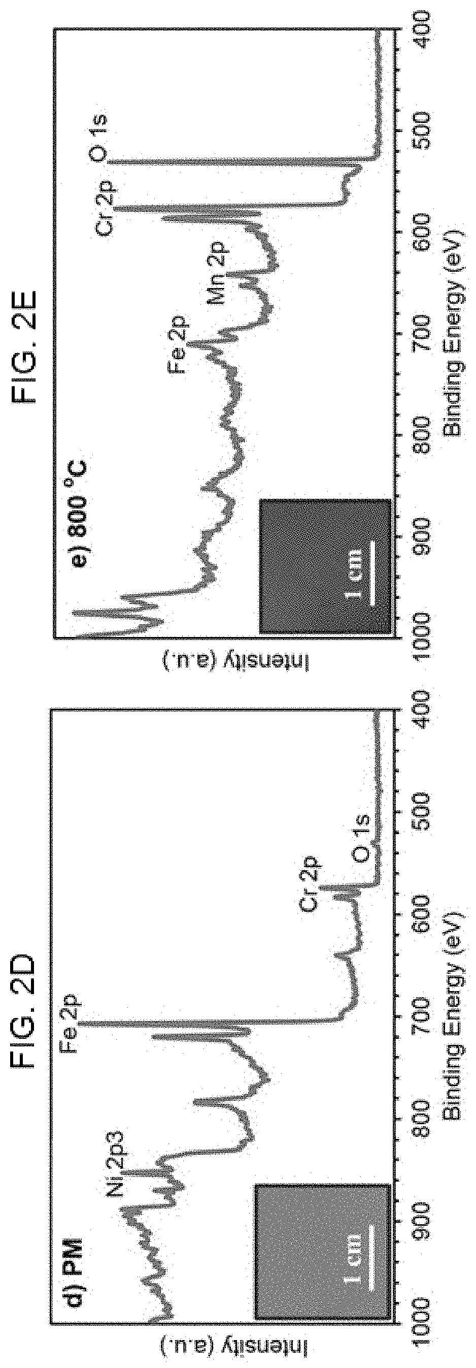
[0061]The morphology and chemical compositions of the structures produced by annealing at 800° C. or 1,000° C. were evaluated using Field emission scanning electron microscope (FE-SEM, TESCAN ultra high resolution) and X-ray photoelectron spectroscopy, XPS (ESCALAB-250Xi System, Thermos-Scientific).

[0062]When a liquid drop comes in contact with the solid surface of high surface energy, then the liquid tends to spread on the surface and ...


PUM


Abstract

A universal, scalable, solvent-free, one-step method for thermal annealing a stainless steel membrane to create a superhydrophilic surface. The superhydrophilic membrane itself, and methods for using it to separate oil and water in an oil and water mixture or for photocatalytic degradation of methylene blue and other organic contaminants.

Description

CROSS-REFERENCE TO RELATED APPLICATION[0001]This application claims priority to U.S. Provisional Application 62 / 642,954, filed Mar. 14, 2018 and which is hereby incorporated by references for all purposes.BACKGROUNDField of the Invention[0002]The invention falls within the fields of chemistry, environmental sciences, and wastewater management.Description of Related Art[0003]The “background” description provided herein is for the purpose of generally presenting the context of the disclosure. Work of the presently named inventor(s), to the extent it is described in this background section, as well as aspects of the description which may not otherwise qualify as prior art at the time of filing, are neither expressly or impliedly admitted as prior art against the present invention.[0004]Integration of selective wettability and photocatalytic activity in a single unit operation is highly desirable for of oily wastewater remediation (i.e., separation of water-insoluble oils and degradatio...

Claims


Application Information

Patent Timeline
IPC IPC(8): B01D71/02B01D61/14C02F1/32C02F1/44C02F101/32
CPCB01D71/022B01D61/147B01D71/024C02F1/32C02F1/444B01D2311/2611B01D2325/36C02F2101/32B01D69/02B01D2325/02B01D69/10B01D69/12C02F2305/10C02F1/44C02F2305/08Y02W10/37B01D2325/02833B01D67/00411B01D69/1071B01D69/108B01D2325/0283
Inventor GONDAL, MOHAMMED A.QATAN, TALAL F.DASTAGEER, MOHAMED A.
Owner KING FAHD UNIVERSITY OF PETROLEUM AND MINERALS
Learn More