Electrode for electrolysis and process for producing the same

Active Publication Date: 2007-02-08
DE NORA PERMELEC LTD
View PDF5 Cites 34 Cited by
  • Summary
  • Abstract
  • Description
  • Claims
  • Application Information

AI Technical Summary

Benefits of technology

[0041] An object of the invention is to provide an electrode for electrolysis which has been produced by coating the surface of a substrate made of a material such as a valve metal, valve-metal-based alloy, silicon, or carbon with a conductive diamond layer especially by CVD and in which the substrate has a surface shape effective in prolonging the electrolytic life of the electrode for electrolysis. Another object of the invention is to provide a process for producing the electrode.
[0061] Due to the use of the substrate having such combinations, the electrodes for electrolysis (conductive diamond electrodes) of the invention have improved durability. The reasons for this are presumed to be as follows.
[0062] (1) The diamond layer has an increased surface area due to the increased surface area of the substrate and, hence, the effective current density during electrolysis can be reduced.
[0063] (2) The increased surface area of the substrate enables a diamond layer to be deposited in an increased amount under the same CVD process conditions and, hence, the effective catalyst amount increases.
[0064] (3) An improved anchoring effect is obtained at the interface between the substrate and the diamond layer.
[0065] The invention proposes optimal surface shapes for a conductive substrate for use in an electrode for electrolysis (conductive diamond electrode) produced by coating the conductive substrate with a diamond layer by any of various methods, in particular, CVD. The surface shapes can improve adhesion between the substrate and the diamond layer and reduce the effective current density during electrolysis. Furthermore, the effective volume of the diamond layer can be increased. Because of these, a diamond electrode which can stably withstand long-term use even in highly corrosive electrolytic solutions can be provided. Therefore, industrial use of this diamond electrode can be expected.

Problems solved by technology

Although electrolytic processes are being practically used as shown above, there are cases where intended reactions do not sufficiently proceed depending on the electrode materials.
In the case where the intended reaction is one involving neither oxygen evolution nor hydrogen evolution, it is necessary to minimize the progress of the water discharge reactions because the discharge of water reduces the efficiency of the intended reaction.
However, this method is not applicable when the equilibrium potential in the intended reaction is nobler than that in the oxygen evolution reaction or is less noble than that in the hydrogen evolution reaction.
For example, this method is not applicable to a treatment for decomposing persistent substances because the oxidation potential for the persistent substances is nobler than the equilibrium potential in oxygen evolution.
Even when an intended reaction can be caused to proceed preferentially by selecting an electrode material as described above, this electrolytic process cannot be practically employed as long as the electrode material selected has insufficient corrosion resistance.
In particular, the corrosion resistance of the anode material on which an oxidation reaction is to be conducted is one of major problems encountered in putting the electrolytic process into practical use.
The materials usable as the substrate of the anode are substantially limited to valve metals, e.g., titanium Ti, and alloys thereof, and the electrode catalysts also are limited to noble metals such as platinum (Pt) and iridium (Ir), oxides of such noble metals, lead oxide (PbO2), and tin oxide (SnO2).
It is, however, known that even when such expensive materials are used, they are consumed depending on the density of the current applied and on the lapse of time and dissolve away in the solution.
However, carbon electrodes are consumable electrodes and are considerably consumed especially in anodic polarization.
Consequently, use of carbon electrodes is limited to applications where consumption is allowable or where there is no substitute material.
However, these electrolytic processes have drawbacks, for example, that the diamond layer separates from the substrate during electrolysis and that the diamond layer is consumed with the continuation of electrolysis and the amount of the diamond thus consumed is proportional to the current density or quantity of electricity.
However, none of these discloses an effect in diamond electrode production.
However, it is necessary to form a diamond layer in a thickness sufficient for maintaining a structure as a free-standing electrode, e.g., about several millimeters, resulting in an exceedingly high electrode production cost.
Even when the free-standing diamond has a thickness of about several millimeters, the strength thereof is insufficient in electrolytic applications where a relatively large electrode is necessary (see A. Fujishima, Y. Einaga, T. N. Rao, and D. A. Tryk, eds., Diamond Electrochemistry, BKC and Elsevier).
However, no electrode having a satisfactory electrode life in industrial fields, in particular, electrolytic processes, has been commercialized.

Method used


Image

  • Electrode for electrolysis and process for producing the same
  • Electrode for electrolysis and process for producing the same
  • Electrode for electrolysis and process for producing the same

Examples


example 1

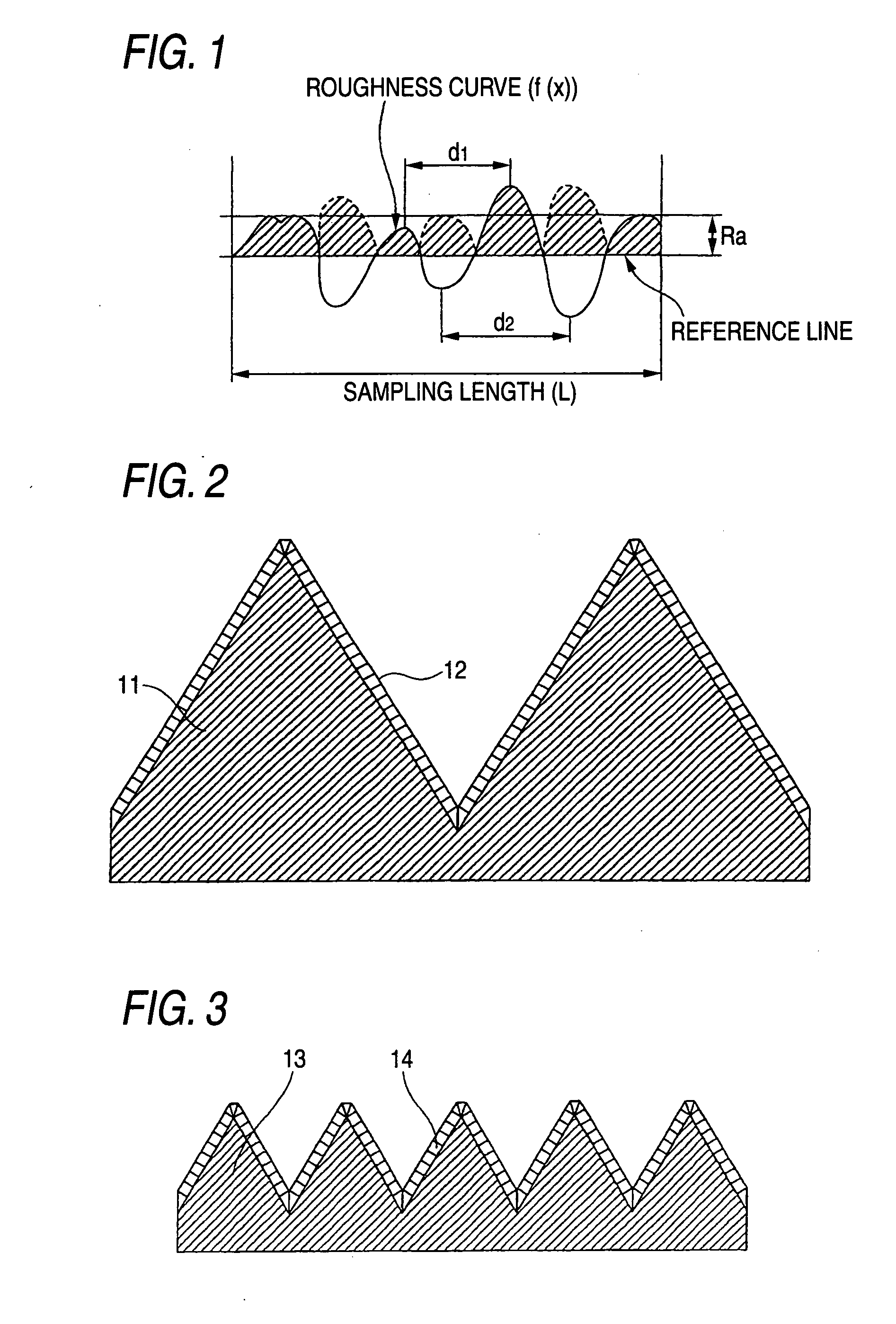
[0102] A niobium metal plate having a size of 30 mm×30 mm and a thickness of 2 mm (substrate sample) was blasted by blowing #60 alumina particles against both sides of the plate using 0.7 MPa compressed air.

[0103] Subsequently, the substrate sample was immersed for 10 minutes in a 60° C. aqueous solution having H2O2 (hydrogen peroxide) of 2 wt % and HF (hydrofluoric acid) of 5 wt %, thereafter subjected to ultrasonic cleaning in pure water at 28 kHz and 300 W for 15 minutes, and then dried. An examination with a laser microscope for surface shape revealed that this substrate sample had an Ra of 3.7 μm and an RSm of 34 μm, which correspond to medium tops / valleys.

[0104] A 3-D image obtained from a laser microscope photograph (1,000 magnifications) of a surface of this conductive substrate is shown in the upper part of FIG. 6, and a profile of that width-direction section of this 3-D image which extends along the depth-direction center is shown in the lower part of FIG. 6.

[0105] A s...

example 2

[0111] A tantalum metal plate having a size of 30 mm×30 mm and a thickness of 2 mm (substrate sample) was blasted by blowing #36 alumina particles against both sides of the plate using 0.5 MPa compressed air. Subsequently, the substrate sample was immersed for 20 minutes in a 60° C. aqueous solution having H2O2 (hydrogen peroxide) of 2 wt % and HF (hydrofluoric acid) of 5 wt %, thereafter subjected to ultrasonic cleaning in pure water at 28 kHz and 300 W for 15 minutes, and then dried. The substrate surface had a shape having an Ra of 11.8 μm and an RSm of 50 μm, which correspond to medium tops / valleys.

[0112] Subsequently, a seeding treatment and diamond layer formation were conducted in the same manners as in Example 1.

[0113] It was ascertained through Raman spectroscopy that a diamond layer had deposited on the substrate. From an electron photomnicrograph of a section, the thickness of the diamond layer was found to be 5 μm. The diamond layer was examined with a laser microscope...

example 3

[0121] Three niobium metal plates having a size of 30 mm×30 mm and a thickness of 2 mm (substrate samples) were blasted by blowing #60 alumina particles against both sides thereof using 0.7 MPa compressed air. Subsequently, the niobium plates were subjected to ultrasonic cleaning in pure water at 28 kHz and 300 W for 15 minutes and then dried. Immediately thereafter, the niobium plates were introduced into a vacuum furnace and heated at a rate of 4° C. / min while maintaining a vacuum of 10-3-10-5 Pa. Thereafter, the first niobium plate was heated to 750° C., held at this temperature for 10 hours, and then allowed to cool to room temperature in the furnace at a rate of 4° C. / min. The second niobium plate was heated to 1,090° C., held at this temperature for 1 hour, and then allowed to cool to room temperature in the furnace at a rate of 4° C. / min. The third niobium plate was heated to 1,090° C., held at this temperature for 1 hour, subsequently further heated to 1,300° C., held at thi...


PUM

PropertyMeasurementUnit
Lengthaaaaaaaaaa
Lengthaaaaaaaaaa
Lengthaaaaaaaaaa

Abstract

The present invention provides an electrode for electrolysis including: a conductive substrate; and a conductive diamond formed on a surface of the conductive substrate, the conductive substrate having at least one surface shape selected from the group consisting of: (a) a surface shape of a combination of an Ra of 100-1,000-μm and an RSm of 50-10,000 μm; (b) a surface shape of a combination of an Ra of 2.5-100 μm and an RSm of 1.5-800 μm, and (c) a surface shape of a combination of an Ra of 0.01-2 μm and an RSm of 0.005-250 μm, and a process for producing the electrode.

Description

FIELD OF THE INVENTION [0001] The present invention relates to electrodes for electrolysis and processes for producing the electrodes. More particularly, the invention relates to electrodes for electrolysis with which substances contained in wastewaters, raw water for drinking water, or the like and exerting adverse influences on the human body or environment can be efficiently decomposed and removed and the synthesis of ozone, persulfuric acid, percarbonic acid, or the like can be efficiently conducted and which are conductive diamond electrodes excellent in durability and profitability when used especially as anodes, and to processes for producing these electrodes. BACKGROUND OF THE INVENTION [0002] An electrolytic process is a process in which electrical energy, which is a clean energy, is utilized and chemical reactions occurring on the electrode surfaces can be controlled. Furthermore, since an oxidation reaction and a reduction reaction proceed at different places, i.e., on th...

Claims


Application Information

Patent Timeline
IPC IPC(8): C25C7/02
CPCB82Y30/00C02F1/46104C02F2001/46138C02F2001/46152C02F2101/30C25B11/0478C02F2101/34C02F2305/08C23C16/0254C23C16/271C23C16/278C02F2101/303C25B11/091
Inventor HOSONUMA, MASASHIUNO, MASAHARUSHIBATA, TOMOYASUNISHIKI, YOSHINORIFURUTA, TSUNETO
Owner DE NORA PERMELEC LTD
Why Eureka
Try Eureka