Eureka AIR delivers breakthrough ideas for toughest innovation challenges, trusted by R&D personnel around the world.

Baroreflex Modulation Based On Monitored Cardiovascular Parameter

Inactive Publication Date: 2007-01-25
CVRX
View PDF99 Cites 191 Cited by
  • Summary
  • Abstract
  • Description
  • Claims
  • Application Information

AI Technical Summary

Benefits of technology

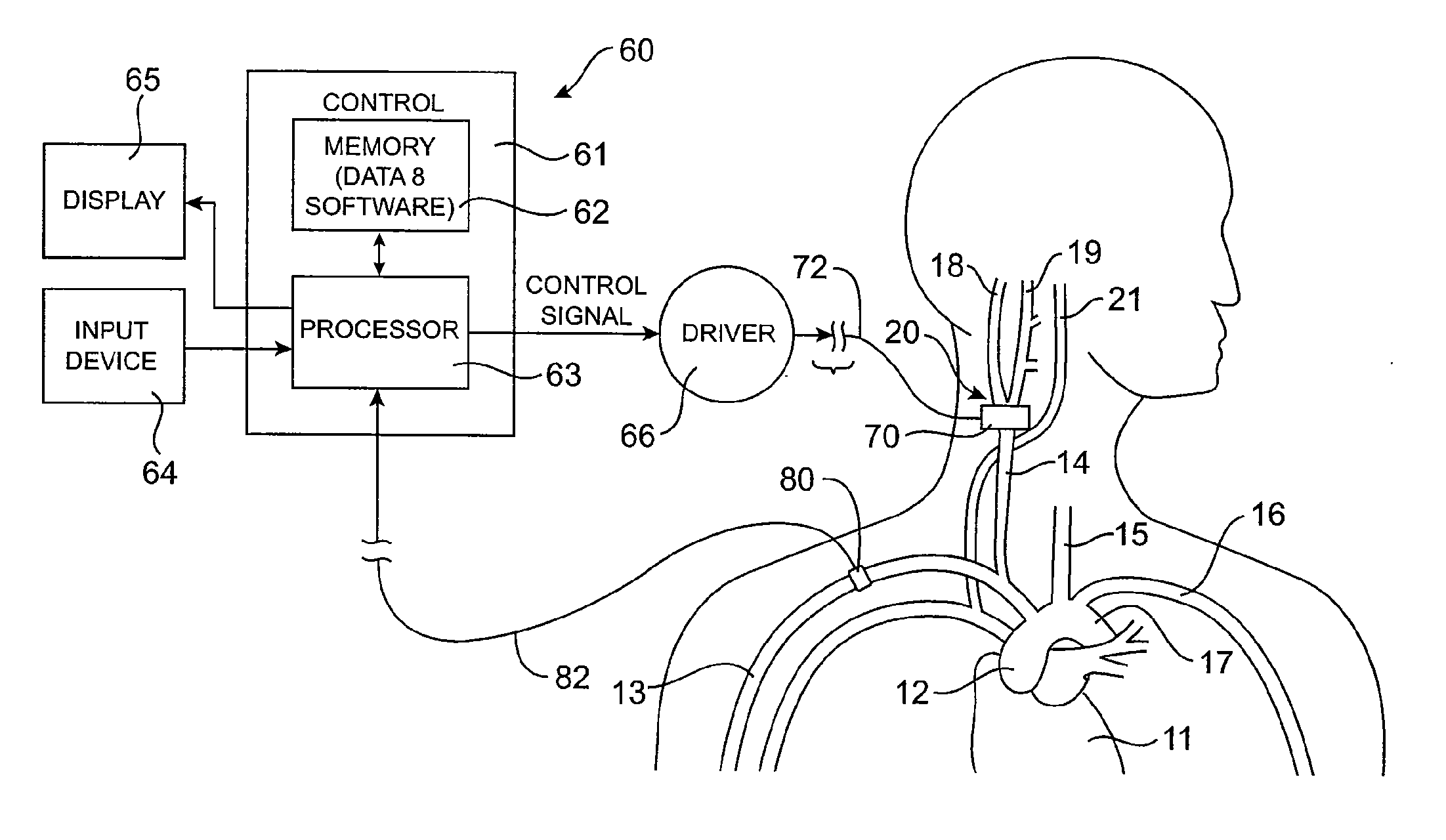
[0014] To address hypertension, heart failure and their associated cardiovascular and nervous system disorders, the present invention provides a number of devices, systems and methods by which the blood pressure, nervous system activity, and neurohormonal activity may be selectively and controllably regulated by activating baroreceptors. By selectively and controllably activating baroreceptors, the present invention reduces excessive blood pressure, sympathetic nervous system activation and neurohormonal activation, thereby minimizing their deleterious effects on the heart, vasculature and other organs and tissues.
[0016] Generally speaking, the baroreceptor activation device may be activated, deactivated or otherwise modulated to activate one or more baroreceptors and induce a baroreceptor signal or a change in the baroreceptor signal to thereby effect a change in the baroreflex system. The baroreceptor activation device may be activated, deactivated, or otherwise modulated continuously, periodically, or episodically. The baroreceptor activation device may comprise a wide variety of devices which utilize electrodes to directly or indirectly activate the baroreceptor. The baroreceptor may be activated directly, or activated indirectly via the adjacent vascular tissue. The baroreceptor activation device will be positioned outside the vascular wall. To maximize therapeutic efficacy, mapping methods may be employed to precisely locate or position the baroreceptor activation device.
[0022] Preferred stretchable electrodes comprise elongated coils, where the coils may stretch and shorten in a spring-like manner. In particularly preferred embodiments, the elongated coils will be flattened over at least a portion of their lengths, where the flattened portion is oriented in parallel to the elastic base. The flattened coil provides improved electrical contact when placed against the exterior of the carotid sinus or other blood vessel.
[0025] As with prior embodiments, the electrode structure preferably includes one or more stretchable electrodes secured to the electrode-carrying surface. The stretchable electrodes are preferably elongated coils, more preferably being “flattened coils” to enhance electrical contact with the blood vessel to be treated. The base is preferably an elastic base, more preferably being formed from an elastomeric sheet. The phrase “flattened coil,” as used herein, refers to an elongate electrode structure including a plurality of successive turns where the cross-sectional profile is non-circular and which includes at least one generally flat or minimally curved face. Such coils may be formed by physically deforming (flattening) a circular coil, e.g., as shown in FIG. 24 described below. Usually, the flattened coils will have a cross-section that has a width in the plane of the electrode assembly greater than its height normal to the electrode assembly plane. Alternatively, the coils may be initially fabricated in the desired geometry having one generally flat (or minimally curved) face for contacting tissue. Fully flattened coils, e.g., those having planar serpentine configurations, may also find use, but usually it will be preferred to retain at least some thickness in the direction normal to the flat or minimally curved tissue-contacting surface. Such thickness helps the coiled electrode protrude from the base and provide improved tissue contact over the entire flattened surface.
[0032] To address low blood pressure and other conditions requiring blood pressure augmentation, the present invention provides electrode designs and methods utilizing such electrodes by which the blood pressure may be selectively and controllably regulated by inhibiting or dampening baroreceptor signals. By selectively and controllably inhibiting or dampening baroreceptor signals, the present invention reduces conditions associated with low blood pressure.

Problems solved by technology

Although each of these alternative approaches is beneficial in some ways, each of the therapies has its own disadvantages.
For example, drug therapy is often incompletely effective.
Some patients may be unresponsive (refractory) to medical therapy.
Drugs often have unwanted side effects and may need to be given in complex regimens.
These and other factors contribute to poor patient compliance with medical therapy.
Drug therapy may also be expensive, adding to the health care costs associated with these disorders.
Likewise, surgical approaches are very costly, may be associated with significant patient morbidity and mortality and may not alter the natural history of the disease.
Baropacing also has not gained acceptance.
These include the invasiveness of the surgical procedure to implant the nerve electrodes, and postoperative pain in the jaw, throat, face and head during stimulation.
In addition, it has been noted that high voltages sometimes required for nerve stimulation may damage the carotid sinus nerves.

Method used


Image

  • Baroreflex Modulation Based On Monitored Cardiovascular Parameter
  • Baroreflex Modulation Based On Monitored Cardiovascular Parameter
  • Baroreflex Modulation Based On Monitored Cardiovascular Parameter

Examples


Embodiment Construction

[0061] The following detailed description should be read with reference to the drawings in which similar elements in different drawings are numbered the same. The drawings, which are not necessarily to scale, depict illustrative embodiments and are not intended to limit the scope of the invention.

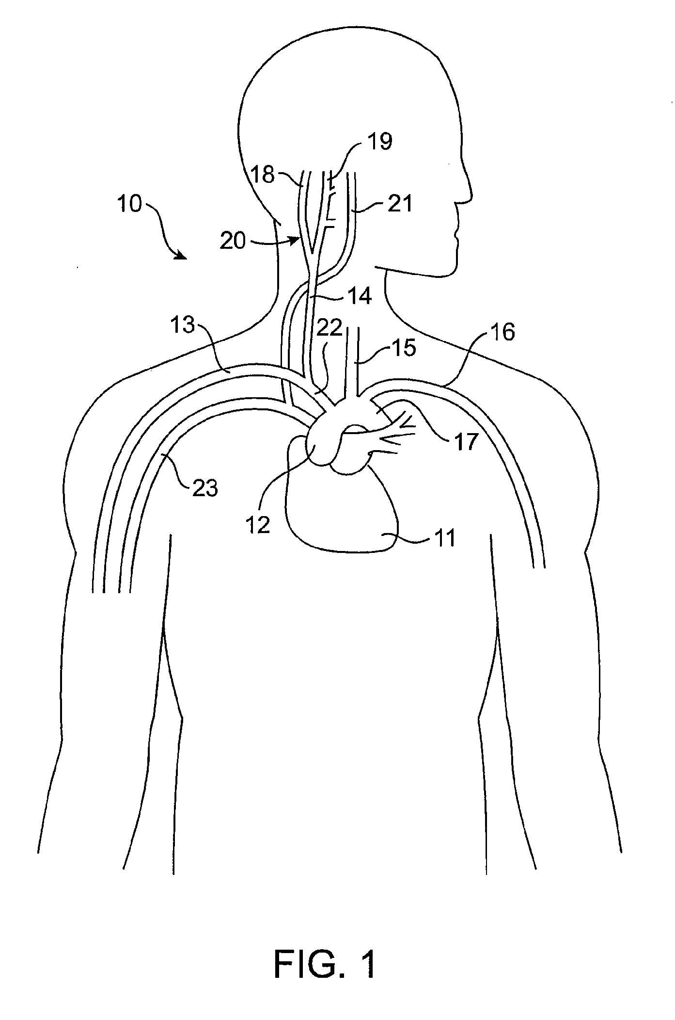
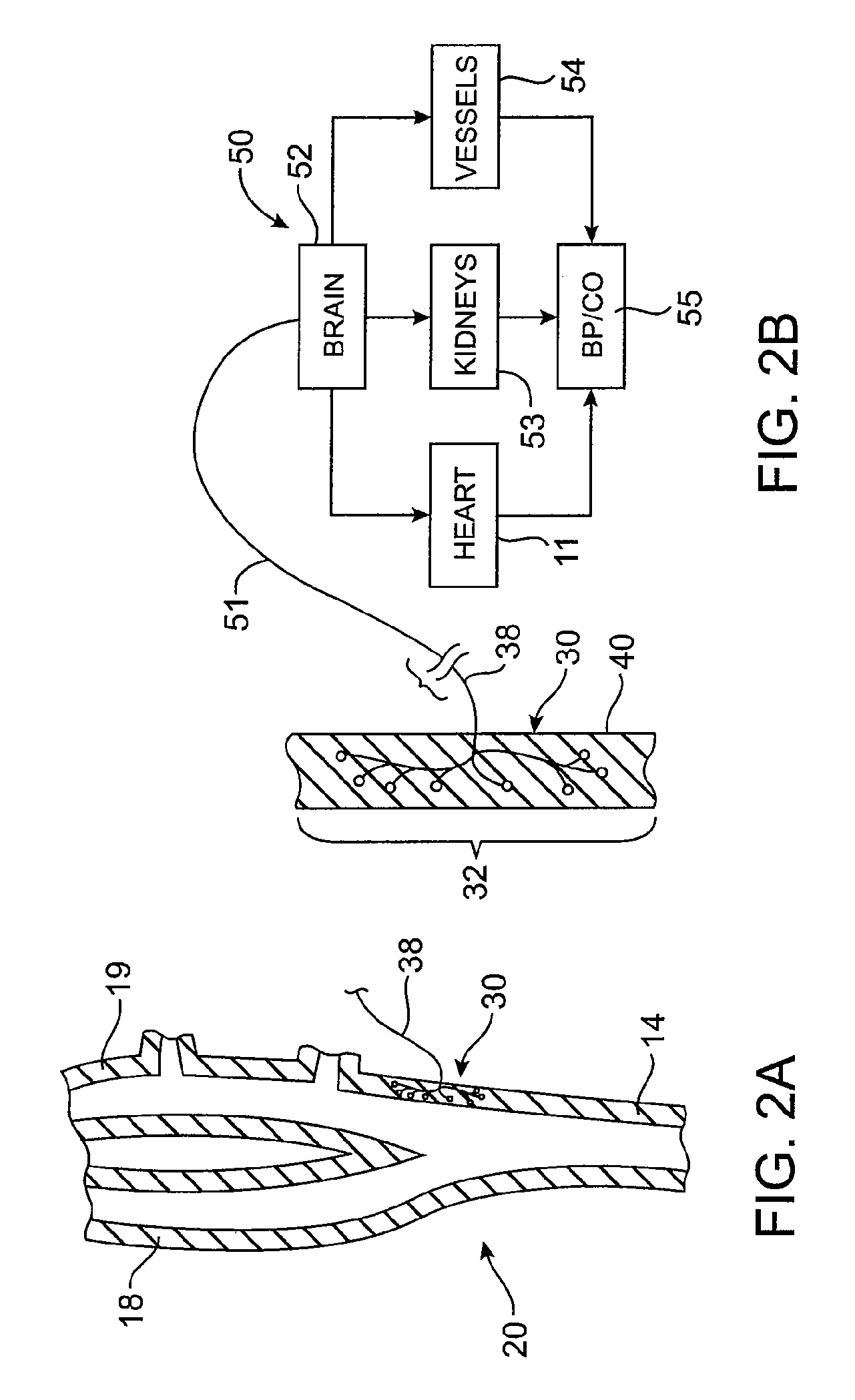
[0062] To better understand the present invention, it may be useful to explain some of the basic vascular anatomy associated with the cardiovascular system. Refer to FIG. 1 which is a schematic illustration of the upper torso of a human body 10 showing some of the major arteries and veins of the cardiovascular system. The left ventricle of the heart 11 pumps oxygenated blood up into the aortic arch 12. The right subclavian artery 13, the right common carotid artery 14, the left common carotid artery 15 and the left subclavian artery 16 branch off the aortic arch 12 proximal of the descending thoracic aorta 17. Although relatively short, a distinct vascular segment referred to as the brachi...


PUM


Abstract

The present invention is a system for providing baroreceptor stimulation comprising, a sensor to sense a physiologic parameter and provide a signal indicative of the physiologic parameter, a baroreceptor activation device, which includes, a pulse generator to intermittently generate a stimulation signal to provide baroreceptor stimulation for a baroreflex therapy, and a control system to adjust the stimulation signal based on the signal indicative of the physiologic parameter such that the stimulation signal provides a desired baroreceptor stimulation corresponding to a desired physiologic parameter.

Description

CROSS-REFERENCES TO RELATED APPLICATIONS [0001] This application is a continuation of U.S. patent application Ser. No. 10 / 402,911 (Attorney Docket No. 021433-000410US), filed on Mar. 27, 2003, which (i) is a continuation-in-part of U.S. patent application Ser. No. 09 / 963,777 (Attorney Docket No. 021433-000120US), filed on Sep. 26, 2001, (ii) which is a continuation-in-part of U.S. patent application Ser. No. 09 / 671,850 (Attorney Docket No. 021433-000100US), filed on Sep. 27, 2000, now U.S. Pat. No. 6,522,926, and (iii) which claimed the benefit of U.S. Provisional Patent Application No. 60 / 368,222 (Attorney Docket No. 021433-000400US), filed on Mar. 27, 2002, the disclosures of each of the above being hereby incorporated by reference in their entirety. The parent application for this application incorporated by reference the disclosures of the following U.S. patent applications: U.S. patent application Ser. No. 09 / 964,079 (Attorney Docket No. 021433-000110US), filed on Sep. 26, 2001...

Claims


Application Information

Patent Timeline
IPC IPC(8): A61N1/00A61N1/05A61N1/36
CPCA61B5/02028A61N1/05A61N1/0551A61N1/056A61N1/08A61N1/36135A61N1/36117A61N1/36185A61N1/3702A61N1/36053A61N1/3611A61N1/36114A61N1/36125
Inventor KIEVAL, ROBERT S.ROSSING, MARTIN A.SERDAR, DAVID J.
Owner CVRX
Why Eureka
Eureka Blog
Learn More