
Flicker Compensation in Lighting Devices

Active Publication Date: 2015-09-24
CRESTRON ELECTRONICS
View PDF4 Cites 6 Cited by
  • Summary
  • Abstract
  • Description
  • Claims
  • Application Information

AI Technical Summary

Benefits of technology

The embodiments aims to minimize the flickering of lamps when dimming them. The technical effect of the patent text is to offer a solution for this problem.

Problems solved by technology

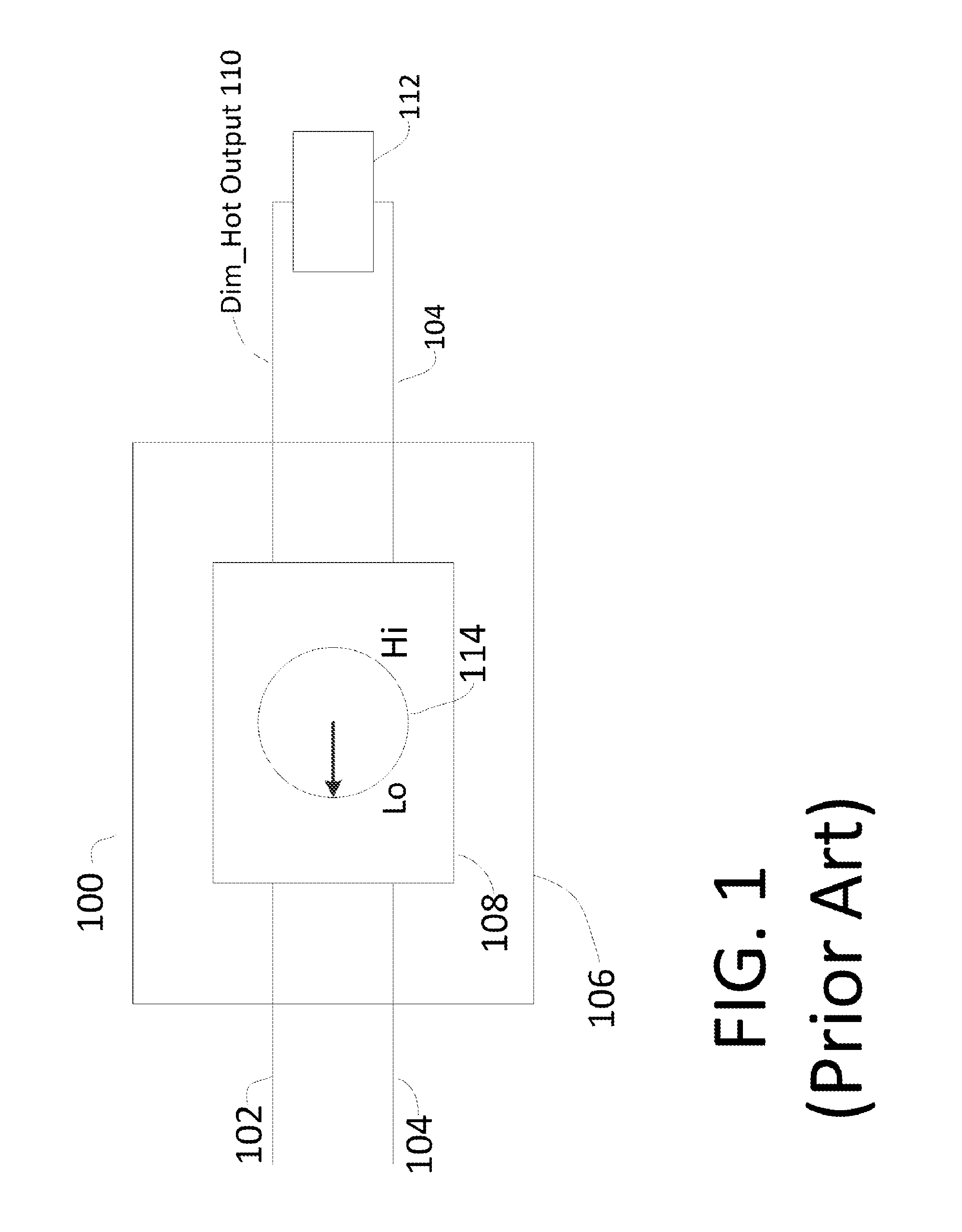
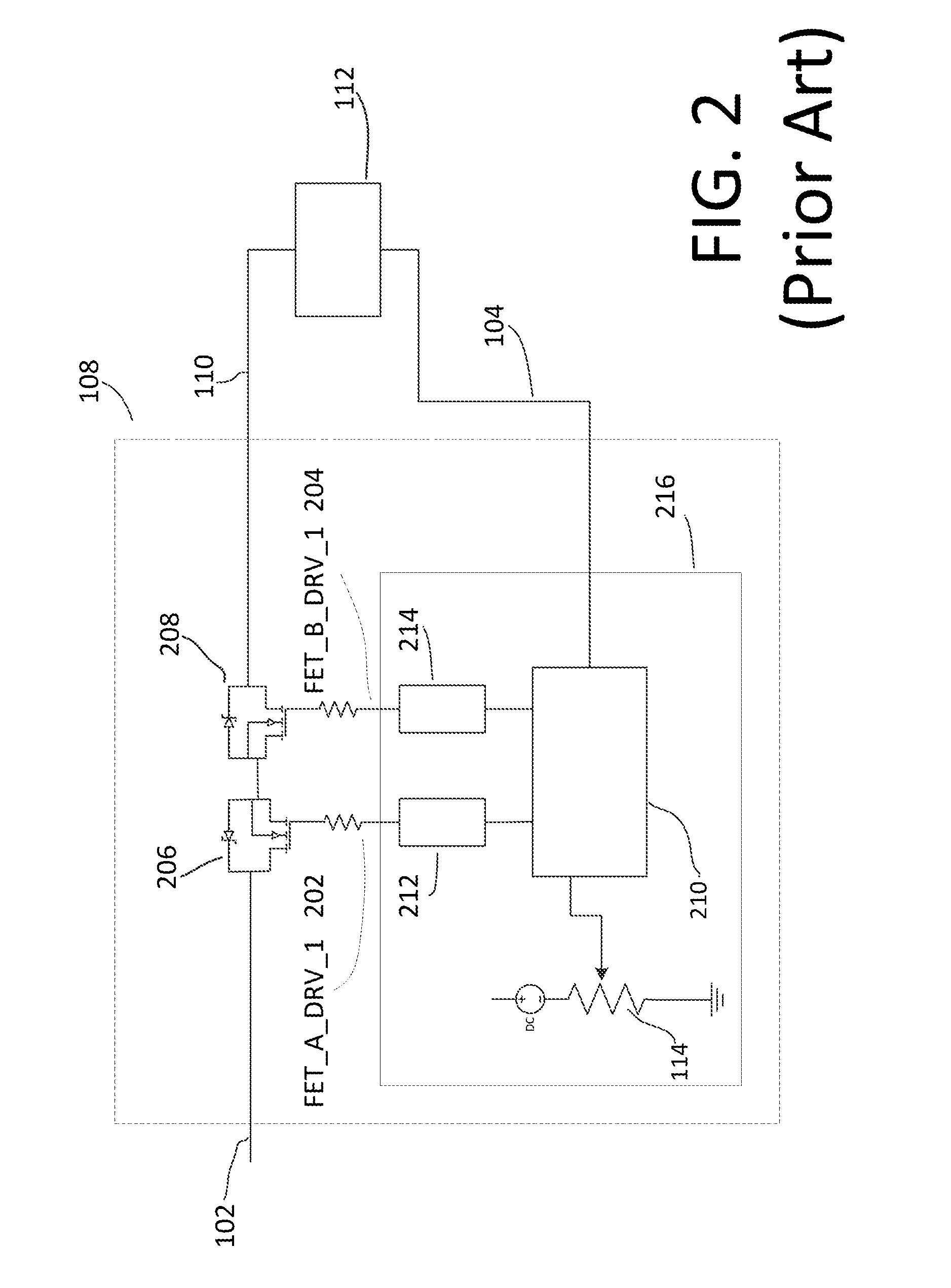
As those of skill in the art can appreciate, while conventional dimming technology has been available for a very long time, there are still some problems with existing technologies.
One such problem in dimming controls is referred to as “flicker.” Flicker is the condition in which the power or voltage that is transferred to the lamp is inconsistent over different cycles of 60 Hz or 50 Hz AC input voltage.
This can cause a reaction to those subjected to the flicker ranging from annoyance to headaches and other maladies.
Both the increase in brightness and decrease in brightness cause flicker.
As those of skill in the art can appreciate, this type of cumbersome approach can lead to premature failure because of the significant number of active components used, as well as required additional power.

Method used


Image

  • Flicker Compensation in Lighting Devices
  • Flicker Compensation in Lighting Devices
  • Flicker Compensation in Lighting Devices

Examples


Embodiment Construction

[0090]The embodiments described herein are generally implemented as part of a lighting control system suitable for use in substantially or wholly reducing or eliminating flicker when using a dimming control feature. Hence, an illustrative dimming control system and its operation according to embodiments will be described herein.

[0091]Unless the context clearly requires otherwise, throughout the description and the claims, the words ‘comprise’, ‘comprising’, and the like are to be construed in an inclusive sense as opposed to an exclusive or exhaustive sense; that is to say, in the sense of “including, but not limited to.”

MODE(S) FOR CARRYING OUT THE INVENTION

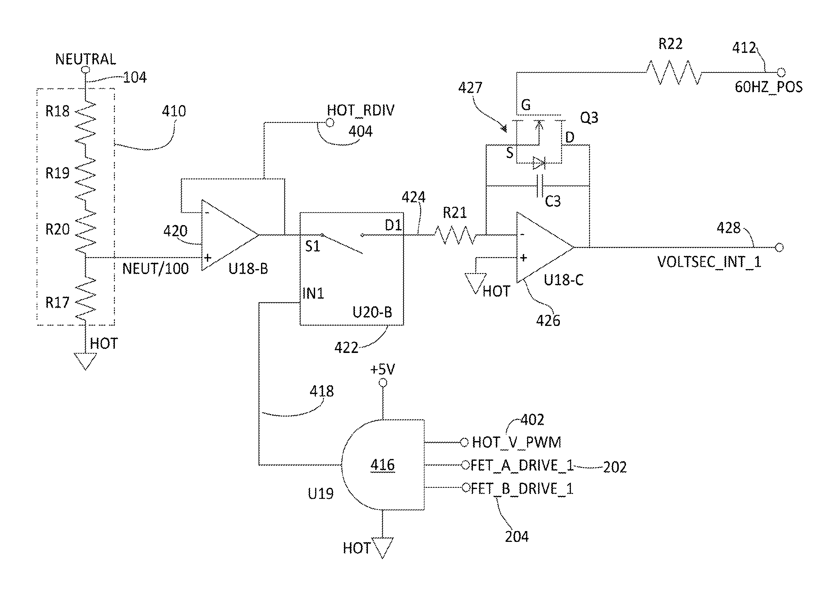
[0092]Aspects of different embodiments are described herein in the context of a circuit for providing dimming controls of incandescent lamps, but is not limited thereto, except as may be set forth expressly in the appended claims.

[0093]FIGS. 4A-4D illustrate voltage-time integrator and constant power circuit (circuit) 400 for us...


PUM


Abstract

A circuit (400) is described herein for controlling dimming of a lamp (112), the circuit comprising a switching circuit (422) configured to provide a chopped portion of an input AC power signal, a resettable inverting integrator circuit (426) configured to integrate the chopped portion of the input AC power signal such that a rise time of an output of the resettable inverting integrator circuit is proportional to a positive amplitude of the chopped portion of the input AC power signal and a fall time of the output of the resettable integrator is proportional to a negative amplitude of the chopped portion, such that an energy provided to the lamp based on the output of the resettable inverting integrator circuit is substantially equivalent from cycle-to-cycle of said input AC power signal regardless of a change in amplitude of the input AC power signal from cycle-to-cycle.

Description

BACKGROUND OF THE INVENTION[0001]1. Technical Field[0002]The aspects of the embodiments described herein relate to an apparatus and method for correcting flicker situations encountered in the use of dimmer units for lighting controls.[0003]2. Background Art[0004]Lighting controls are prevalent in both home and commercial applications. Some lighting controls are very simple, e.g., on / off switches, but others include remote operation and dimming controls, which can be manual or automatic. Regardless of how the dimming controls are operated, it is important that dimming controls operate properly. As those of skill in the art can appreciate, while conventional dimming technology has been available for a very long time, there are still some problems with existing technologies.[0005]One such problem in dimming controls is referred to as “flicker.” Flicker is the condition in which the power or voltage that is transferred to the lamp is inconsistent over different cycles of 60 Hz or 50 Hz ...

Claims


Application Information

Patent Timeline
IPC IPC(8): H05B37/02
CPCH05B37/02H05B39/047H05B47/10H05B47/17Y02B20/00
Inventor TORRE, JOHN
Owner CRESTRON ELECTRONICS
Learn More