
Cold plate apparatus and method of fabrication thereof with a controlled heat transfer characteristic between a metallurgically bonded tube and heat sink for facilitating cooling of an electronics component

a technology of heat transfer characteristic and heat sink, which is applied in the direction of electrical apparatus construction details, light and heating apparatus, laminated elements, etc., can solve the problems of inability to achieve practical approaches, and achieve the effects of good thermal conductor, good thermal conductor, and limited corrosion

Inactive Publication Date: 2007-01-25
IBM CORP
View PDF14 Cites 54 Cited by
  • Summary
  • Abstract
  • Description
  • Claims
  • Application Information

AI Technical Summary

Benefits of technology

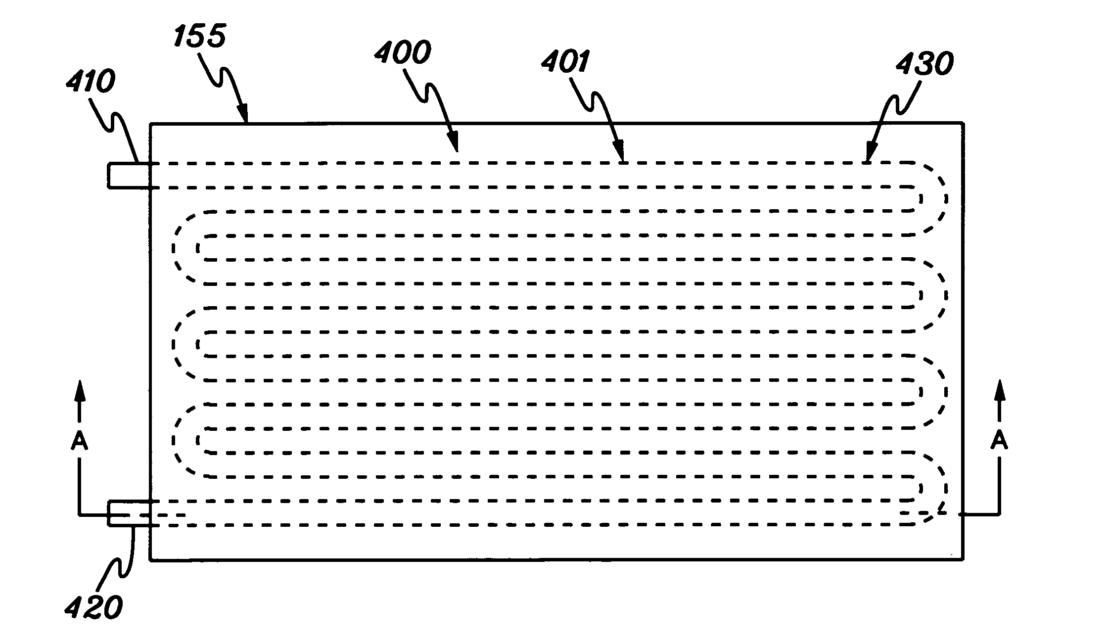
[0006] One such cooling apparatus would be an aluminum cold plate with embedded copper tubes. Copper tubes can be embedded in aluminum cold plates by various mechanical means. For example, fabricated copper tubes could be mechanically coupled or soldered in place within one or more aluminum cold plate parts, which are then assembled around the copper tubing. A less expensive means for manufacturing such an assembly, however, is desirable. One cost-effective technique would be to cast an aluminum heat sink member directly around one or more copper tubes, which define the channels through which coolant is to pass. The use of copper advantageously limits corrosion resulting from the use of water or other aqueous fluids as coolant, while aluminum for the cold plate is a good thermal conductor, low cost and lightweight. This approach, however, is not practical since molten aluminum reacts eutectically with copper to dissolve copper tubing at a very rapid rate.
[0007] These shortcomings of the prior art are overcome and additional advantages are provided through a method of fabricating a cold plate apparatus. The method includes: providing a tube comprising a first metal, the tube having a first end and a second end with a heat transfer region disposed therebetween; positioning the heat transfer region of the tube within a mold and casting a heat sink member around the heat transfer region of the tube by contacting a second metal in molten form over the heat transfer region of the tube, wherein the second metal has a lower melting point than the first metal, the first metal of the tube and the molten second metal react peritectically during casting of the heat sink member to form an alloy layer between the tube and the heat sink member in the heat transfer region of the tube, and a metallurgical bond is formed between the tube and the heat sink member in the heat transfer region of the tube with cooling of the molten second metal, and wherein the first end and the second end of the tube extend from the heat sink member; and controlling the casting of the heat sink member to minimize a thickness of the alloy layer formed between the tube and the heat sink member in the heat transfer region of the tube, wherein the minimizing the thickness of the alloy layer enhances a heat transfer characteristic of the metallurgical bond formed between the tube and the heat sink member.
[0008] In another aspect, a cold plate apparatus for facilitating cooling of a heat generating electronics component is provided. The cold plate apparatus includes a tube and a casted heat sink member. The tube comprises a first metal and has a first end and a second end with a heat transfer region disposed therebetween. The casted heat sink member comprises a second metal and surrounds the heat transfer region of the tube, with the first end and the second end of the tube extending from the casted heat sink member. A metallurgical bond exists between the tube and the heat sink member in the heat transfer region of the tube. The cold plate apparatus further includes an alloy layer between the tube and the casted heat sink member in the heat transfer region of the tube. The alloy layer was formed during casting of the heat sink member by the first metal of the tube and the second metal of the heat sink member reacting peritectically, and the thickness of the alloy layer was minimized during casting of the heat sink member to enhance a heat transfer characteristic of the metallurgical bond between the tube and the heat sink member in the heat transfer region of the tube.
[0009] Still further, a fluid-cooled electronics apparatus is provided. This apparatus includes a heat generating electronics component, and a cold plate apparatus with a surface thereof coupled to a surface of the heat generating electronics component for facilitating removal of heat from the heat generating electronics component. The cold plate apparatus includes a tube and a casted heat sink member. The tube comprises a first metal, and has a first end and a second end with a heat transfer region disposed therebetween. The casted heat sink member comprises a second metal, and the member surrounds the heat transfer region of the tube. The first end and the second end of the tube extend from the casted heat sink member. A metallurgical bond exists between the tube and the heat sink member in the heat transfer region of the tube. The cold plate apparatus further includes an alloy layer disposed between the tube and the casted heat sink member in the heat transfer region of the tube, wherein the alloy layer was formed during casting of the heat sink member by the first metal of the tube and the second metal of the heat sink reacting peritectically. The thickness of the alloy layer was minimized during casting of the heat sink member to enhance a heat transfer characteristic of the metallurgical bond between the tube and the heat sink member in the heat transfer region of the tube.

Problems solved by technology

This approach, however, is not practical since molten aluminum reacts eutectically with copper to dissolve copper tubing at a very rapid rate.

Method used


Image

  • Cold plate apparatus and method of fabrication thereof with a controlled heat transfer characteristic between a metallurgically bonded tube and heat sink for facilitating cooling of an electronics component
  • Cold plate apparatus and method of fabrication thereof with a controlled heat transfer characteristic between a metallurgically bonded tube and heat sink for facilitating cooling of an electronics component
  • Cold plate apparatus and method of fabrication thereof with a controlled heat transfer characteristic between a metallurgically bonded tube and heat sink for facilitating cooling of an electronics component

Examples


Embodiment Construction

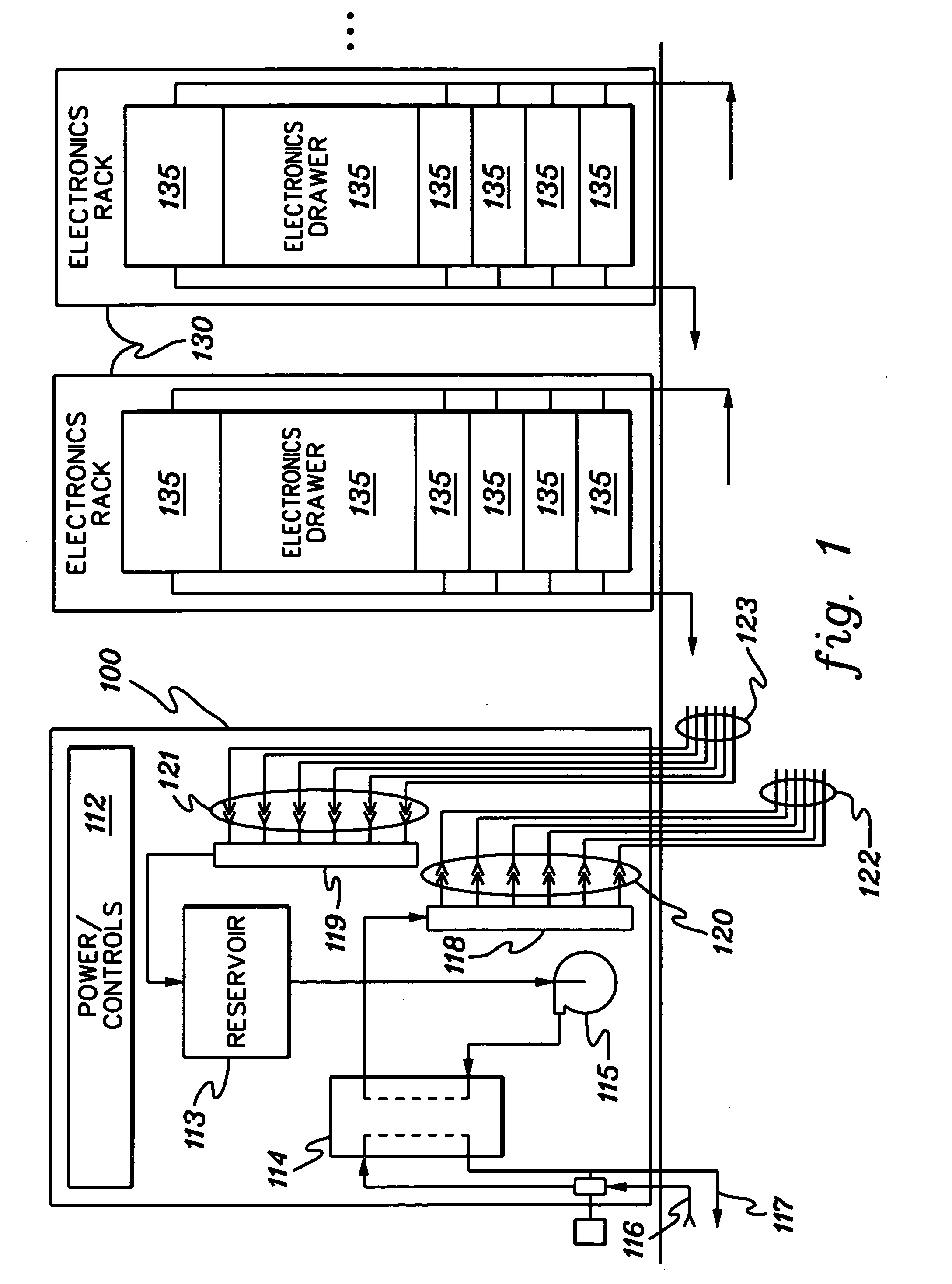
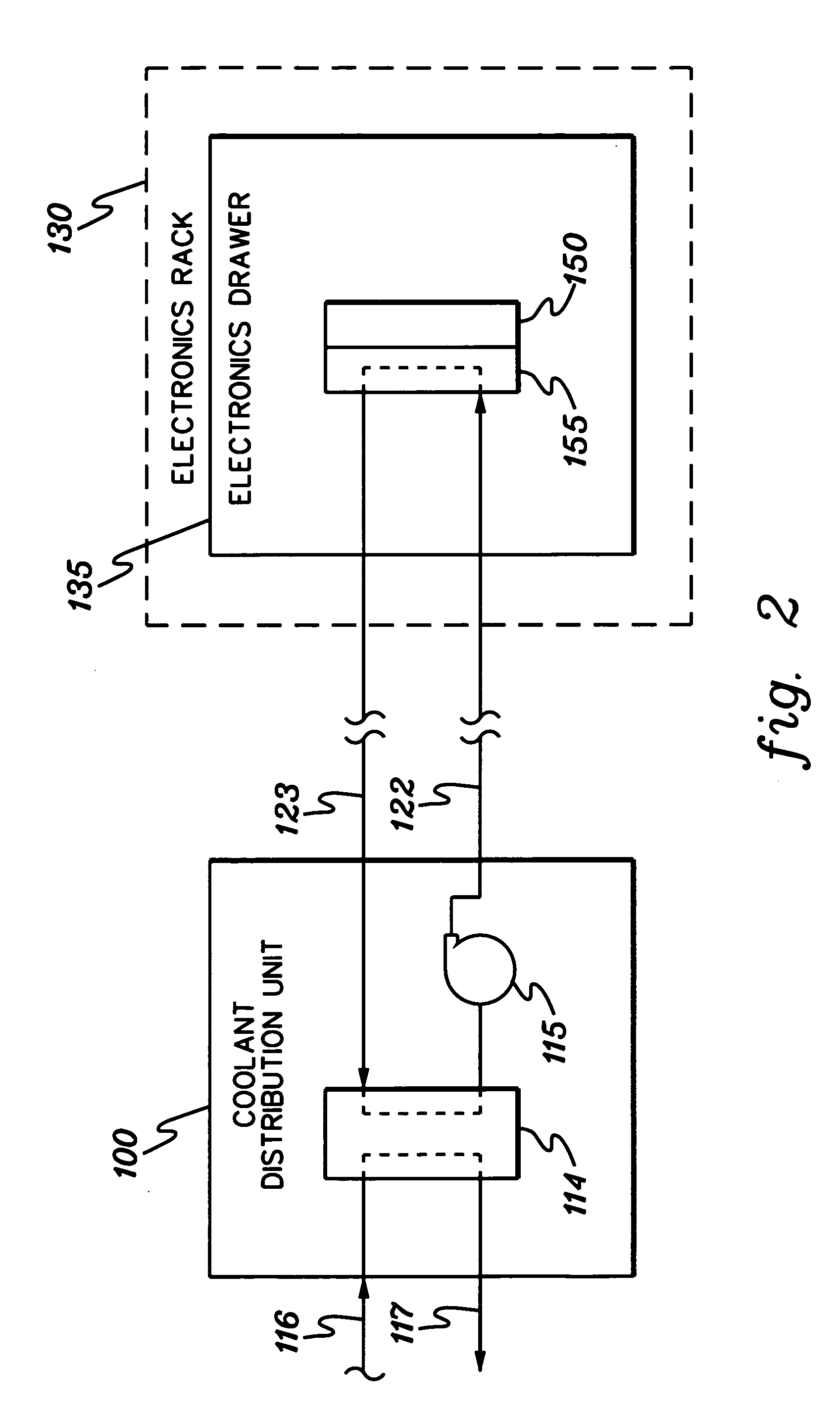
[0021] As used herein, “electronics subsystem” comprises any housing, compartment, drawer, blade, etc., containing one or more heat generating components of a computer system or other electronics system requiring cooling. The term “electronics rack” includes any frame, rack, blade server system, etc., having a heat generating component of a computer system or electronics system, and may be, for example, a stand alone computer processor having high, mid or low end processing capability. In one embodiment, an electronics rack may comprise multiple electronics subsystems, each having one or more heat generating electronics components requiring cooling. Each “heat generating electronics component” may comprise an electronic device, an electronics module, an integrated circuit chip, etc.

[0022] One example of coolant within a cooling system in accordance with an aspect of the present invention is water. However, the concepts disclosed herein are readily adapted to use with other types of...


PUM

PropertyMeasurementUnit
thicknessaaaaaaaaaa
temperatureaaaaaaaaaa

Abstract

Cold plate apparatuses and methods of fabrication are provided for facilitating cooling of an electronics component. The fabrication approach includes: forming a tube with a first metal and having first and second ends with a heat transfer region disposed therebetween; positioning the heat transfer region of the tube within a mold and casting a heat sink member around the tube by contacting a second metal in molten form over the tube, wherein the first and second metals react peritectically to form an alloy layer between the tube and the heat sink member, and a metallurgical bond is formed between the tube and heat sink member with cooling of the molten second metal; and controlling casting of the heat sink member to minimize a thickness of the alloy layer to enhance a heat transfer characteristic of the metallurgical bond formed between the tube and the heat sink member.

Description

TECHNICAL FIELD [0001] The present invention relates generally to heat transfer mechanisms, and more particularly, to cooling apparatuses and methods of fabrication thereof for removing heat generated by one or more electronic devices, modules and systems. Still more particularly, the present invention relates to cold plate apparatuses and methods of fabrication thereof with a controlled heat transfer characteristic across a metallurgical bonded tube and casted heat sink formed by peritectic reaction of the tube and heat sink. BACKGROUND OF THE INVENTION [0002] As is known, operating electronic devices produce heat. This heat should be removed from the devices in order to maintain device junction temperatures within desirable limits. Failure to remove the heat thus produced results in increased device temperatures, potentially leading to thermal runaway conditions. Several trends in the electronics industry have combined to increase the importance of thermal management, including he...

Claims


Application Information

Patent Timeline
Patent Type & Authority Applications(United States)
IPC IPC(8): H05K7/20
CPCH05K7/20254Y10T29/49359Y10T29/49373Y10T29/49393Y10T29/49369Y10T29/4935Y10T29/49364Y10T29/49368Y10T29/49377
Inventor LEHMAN, BRET W.SCHMIDT, ROGER R.SINGH, PRABJIT
Owner IBM CORP
Learn More