
Free curved surface precision machining tool

a technology of precision machining and curved surfaces, which is applied in the direction of manufacturing tools, milling cutters, grinding machine components, etc., can solve the problems of increasing the number of axes, complicated and difficult type of program creation, and inability to perform high-precision and high-quality machining, so as to maintain the sharpness of the tool machining section, the effect of constant moving speed and driving torqu

Inactive Publication Date: 2007-01-04
RIKEN +2
View PDF5 Cites 0 Cited by
  • Summary
  • Abstract
  • Description
  • Claims
  • Application Information

AI Technical Summary

Benefits of technology

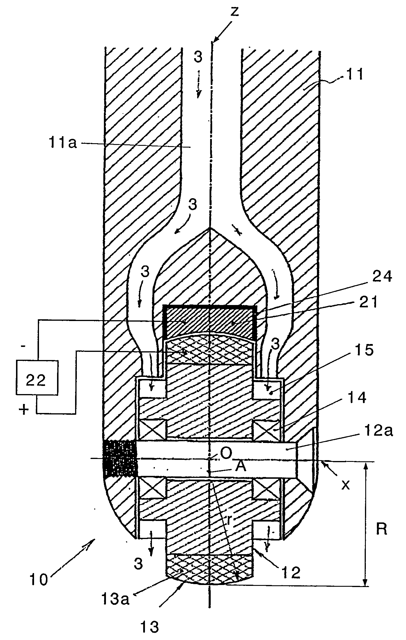
[0021] The present invention has been provided to resolve the above various problems. Specifically, it is an object of the present invention to provide a free curved surface precision machining tool capable of efficiently precision-machining a free curved surface using a versatile 3-axis NC machining apparatus, by dispersing the moving trajectory of the contact surface of a tool machining section and achieving a constant moving speed and driving torque so as to maintain the sharpness of the tool machining section, to achieve uniform wear and a self-correction function thereof, and to decrease the wearing speed, whereby the accuracy of form of the tool machining section can be maintained continuously.
[0025] The convex machining surface of the drum-shaped tool is made of a grindstone or a cutter. The grindstone includes a metal in its bonding material. Moreover, the free curved surface precision machining tool has a non-machining section for protecting the end of the convex machining surface without direct involvement in machining, the non-machining section being adjacent to the convex machining surface of the drum-shaped tool. The non-machining section is made of material wearing out more easily than the grindstone bonding material so as not to damage the surface to be machined and includes a conductive material in its material.
[0032] According to the above configuration of the present invention, the free curved surface precision machining tool precision-machines a surface to be machined with the convex machining surface in contact therewith by rotation around the axis z and the convex machining surface is rotated around the orthogonal axis x so as to disperse the machining position of the convex machining surface. Therefore, the free curved surface precision machining tool is capable of efficiently precision-machining a free curved surface using a versatile 3-axis NC machining apparatus by dispersing the moving trajectory of the contact surface of the tool machining section and achieving a constant moving speed and driving torque so as to maintain the sharpness of the tool machining section, to achieve uniform wear and a self-correction function thereof, and to decrease the wearing speed, whereby the accuracy of form of the tool machining section can be maintained continuously.

Problems solved by technology

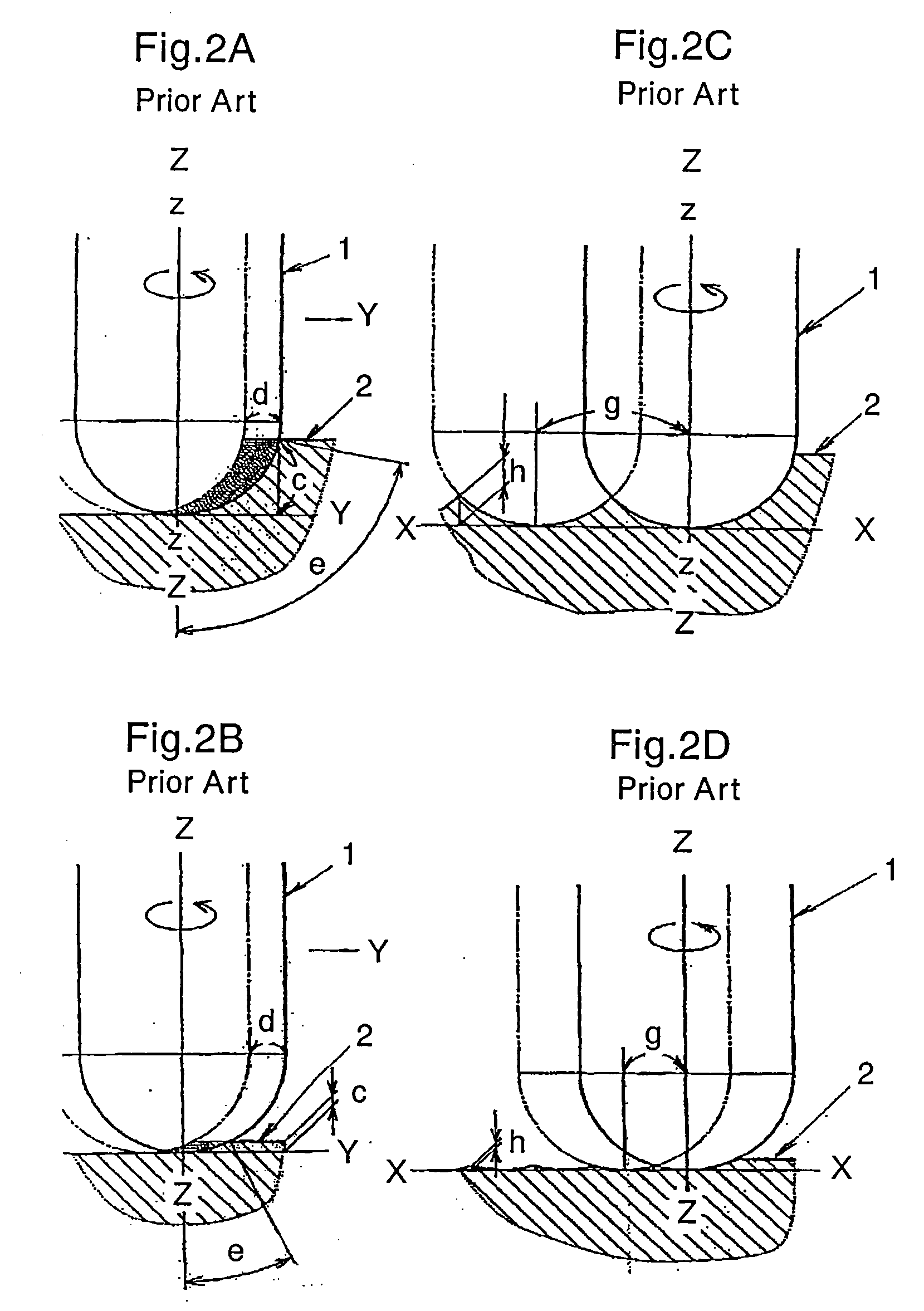
Moreover, the radius of rotation significantly depends upon the position of the machining surface, and thus the circumferential speed and the rotation load largely fluctuate, which leads to a problem that the precision machining (high-precision and high-quality machining) cannot be performed.
In addition, the free curved surface machining tool 1 has a problem that there is a need to maintain sharpness and an accurate spherical surface of the tool machining surface on a constant basis in order to achieve the machining function and precision.
This kind of program creation, however, is complicated and difficult, and further the increase in the number of axes requires an advanced technique in manufacturing the machining apparatus.
This leads to a problem that the multi-axis NC machining apparatus having four or more axes capable of precision machining becomes expensive and poor in versatility.
Moreover, as well as the narrow contact surface e, the peripheral speed and the required driving torque undergo drastic changes according to the magnitude of the distance of the contact surface e from the axis (radius of rotation), thereby causing problems of irregularity in the roughness of the surface to be machined, a chatter mark (caused by vibration), or a decrease in machining accuracy.
On the other hand, the narrowing of the contact surface e causes a local convergence of the contact position or frequency of the machining tool according to the feature of the free curved surface to be machined, which results in a local convergence of portions where the machining function (the sharpness) declines and of deformations caused by contact friction, by which the deformations are reverse-transferred to the surface to be machined or the surface is damaged.
It is, however, generally hard to correct the deformation in a situation where the deformation from the spherical surface is significant.
Unless the axis z can be inclined arbitrarily, however, the grinding section is continuously and systematically corrected by using a setting value previously incorporated into the program, by which a large part of the spherical machining section is removed wastefully.
Therefore, it leads to a problem that there is no other choice but to select a measure to shift the pick feed g by a half pitch or decrease it, though the machining time thereby increases.
Moreover, while the accuracy of machining position can be improved by decreasing the spherical radius of the machining tool, it leads to a problem that the machining time increases as described above.

Method used


Image

  • Free curved surface precision machining tool
  • Free curved surface precision machining tool
  • Free curved surface precision machining tool

Examples


first embodiment

[0082] Referring to FIG. 11, there is shown a diagram of a profile of roughness of a surface machined by the free curved surface precision machining tool according to the present invention. Referring to FIG. 12, there is shown a macrophotograph of the machined surface.

[0083] The work is made of steel for a molding die (stainless steel HRC 42) and the grindstone is a cast iron bond CBN#4000 grindstone (20 mm in diameter and 8 mm in thickness). The work was machined under the machining conditions listed in Table 1: a spindle rotation speed of 1500 rpm, a feed speed of 100 mm / min, a pitch of 0.1 mm, and a depth of the cut of 10 μm / pass.

TABLE 1Machining condotionsspindle rotation speed1500rpmfeed speed100mm / minpich0.1mmcut depth10μm / pass

[0084] The surface roughness after the machining is 0.0188 μmRa or 0.1392 μmRy as shown in Table 2. From this result, it has therefore been confirmed that an excellent mirror surface can be obtained by using the #4000 grindstone in the free curved sur...


PUM

PropertyMeasurementUnit
diameteraaaaaaaaaa
diameteraaaaaaaaaa
depthaaaaaaaaaa

Abstract

A free curved surface precision machining tool for precision-machining a surface to be machined with the lower end in contact therewith by rotation around an axis x. It includes a drum-shaped tool having a rotation axis x orthogonal to the axis z and rotationally driven around the rotation axis x. This drum-shaped tool has a convex machining surface in the form of an arcuate rotary body obtained by rotating an arc of a radius r with the center at the intersection O between the axis z and the rotation axis x around the rotation axis x. The convex machining surface contacts the surface to be machined to precision-machine the latter, while the convex machining surface is rotated around the orthogonal axis x so as to disperse the machining position of the convex machining surface.

Description

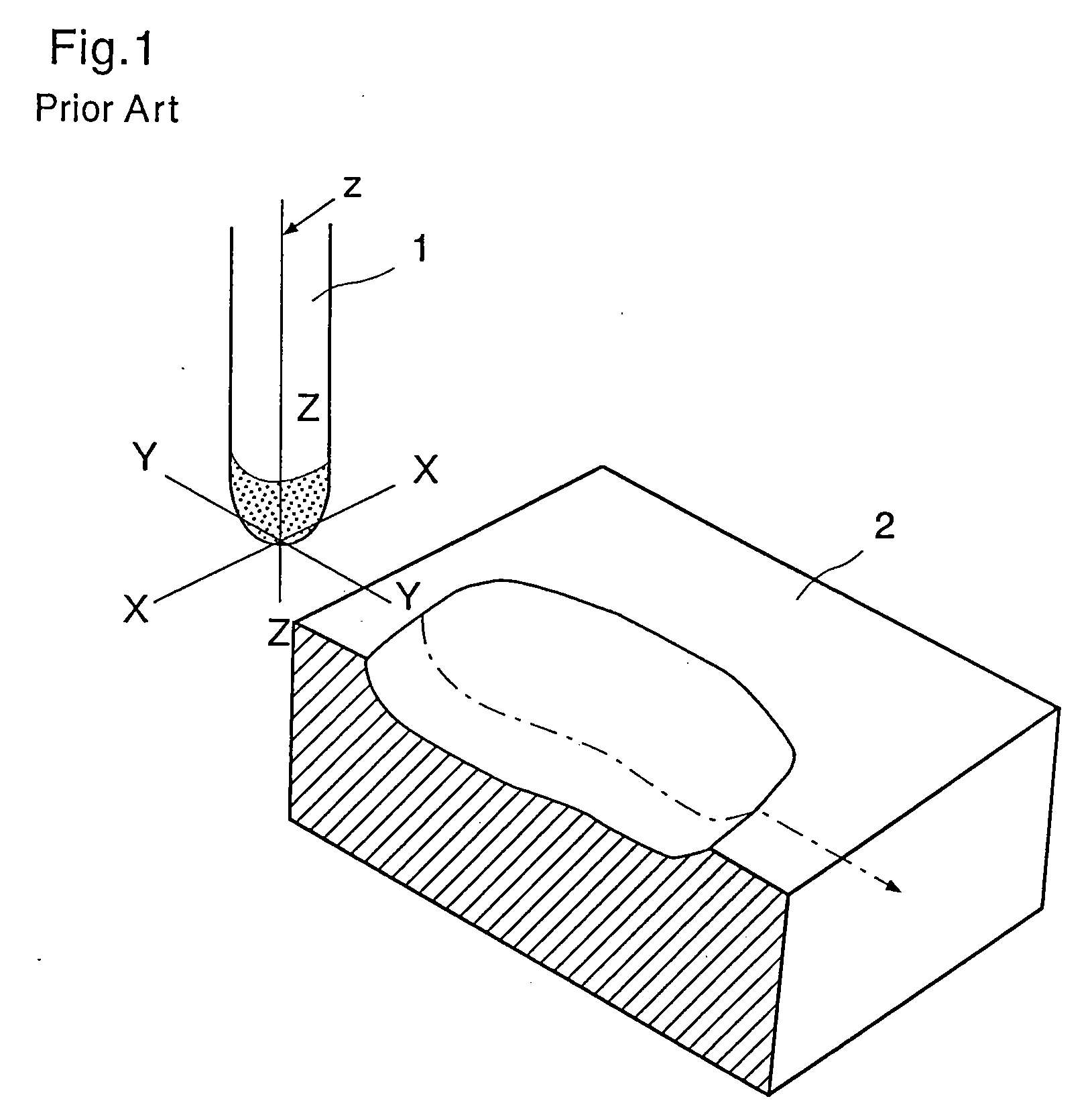
BACKGROUND OF THE INVENTION [0001] 1. Field of the Invention [0002] The present invention relates to a free curved surface precision machining tool for precision-machining a free curved surface (more specifically, for precision-removing the free curved surface with grinding or cutting), having a convex machining section in the form of an arcuate rotary body at the lower end. [0003] 2. Description of the Related Art [0004] Referring to FIG. 1, there is typically shown machining (removal machining) of a free curved surface with a conventional free curved surface machining tool. The conventional free curved surface machining tool 1 is, for example, a ball nose grindstone or a ball end mill, which has a spherical machining surface at the lower end and is configured to rotate around the axis z. A free curved surface 2 is a part of, for example, a molding die, an aspherical lens, or the like. With high-speed rotation around the axis z, the free curved surface machining tool 1 machines the...

Claims


Application Information

Patent Timeline
Patent Type & Authority Applications(United States)
IPC IPC(8): B24B49/00B24B1/00B23C3/16B23C5/10B24B41/04B24D7/10B24D7/18
CPCB23C3/16B24B41/04B23C5/1009
Inventor OMORI, HITOSHIYAMAKI, HIDENORIMATSUZAWA, TAKASHI
Owner RIKEN
Learn More