
Accelerated steel cutting methods and machines for implementing such methods

a technology of steel cutting and accelerated steel, which is applied in the direction of manufacturing tools, soldering devices, auxiliaries welding devices, etc., can solve the problems of not only cutting the workpiece, the process of cutting steel is very slow and tedious, and the cutting torch tends to cut not only the workpiece, so as to increase the rate at which metal flame cutting can be accomplished

Inactive Publication Date: 2006-09-21
PASULKA MATTHEW P
View PDF21 Cites 3 Cited by
  • Summary
  • Abstract
  • Description
  • Claims
  • Application Information

AI Technical Summary

Benefits of technology

The present invention provides an improved method for cutting metal that increases the rate at which flame cutting of metal can be accomplished. The invention uses a cutting torch with a tip capable of selectively discharging two streams of different gases from two different gas supplies, positioning the cutting torch in an opposition relationship to the metal and heating the metal until it reaches a molten state. The high pressure gases are then directed at the molten metal, expelling it from the cutting torch. The invention also provides an apparatus for cutting metal that is well-suited for use in ship environments. The invention is particularly well-suited for cutting template metal pieces and abstract shapes. The apparatus includes a cutting torch with a high-pressure gas supply and a motive device that causes relative movement between the cutting torch and the preheated metal. The invention provides a faster and safer method for cutting metal, and reduces or alleviates the problems caused by paint, rust, or mill scale on the metal surface.

Problems solved by technology

The process of cutting steel is therefore a very slow and tedious process.
Although these machines are much quicker than conventional cutting torch machines, they are complex and very expensive to own and operate.
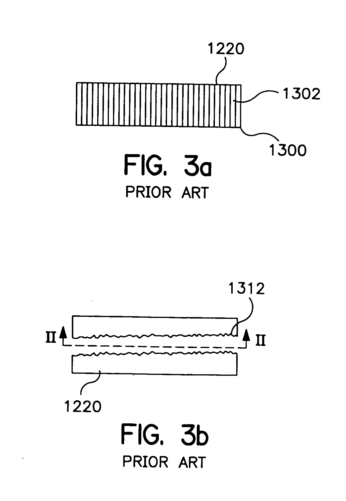
Another disadvantage of the current cutting machines and methods is that the due to the generally perpendicular positioning of the cutting torch tip or plasma arc tip with respect to the cutting surface, the cutting torch tends to cut not only the work piece but also the member that holds the work piece in place.
Similarly, when a steel plate is on the side of a ship or attached or welded to a frame or other steel members, the frame or other steel members are damaged by the cutting torches when cutting the steel plate.
Still another disadvantage of conventional cutting machines and methods is that portions of the work piece becomes insulated from the heat of the flame and flowing oxygen which causes the prior art cutting machines to lose the cut, slow down, or have imperfect cuts that have to be re-cut.
Another reason is the occasionally improper setting of the torch height or heat output, either by the operator or by the computer numerical control (CNC).

Method used


Image

  • Accelerated steel cutting methods and machines for implementing such methods
  • Accelerated steel cutting methods and machines for implementing such methods
  • Accelerated steel cutting methods and machines for implementing such methods

Examples


Embodiment Construction

[0057] U.S. Pat. No. 5,922,144, which is directed to a method for cutting metal, is hereby incorporated by reference.

[0058] In order to cut metal at a constant rate, several factors must be controlled. In the present invention, the new position of the cutting torch, the higher pressures of the gases, and the different heat created by burning the combustible gas with high-pressure oxygen, are some of the factors which must be controlled. For instance, the angle of incidence (.alpha..sub.i) of the cutting torch is changed by rotating the cutting torch flame from the cutting torch tip about a fixed point. The smaller the angle of incidence, the more heat that is transferred to a smaller, localized area of metal. Heat to an area of metal may also be regulated by moving the tip closer to the metal.

[0059] The following discussion is directed to a method for cutting steel according to the present invention.

[0060] Referring to FIGS. 13a-13d, a cutting torch 1000 is used to pre-heat an ar...


PUM

PropertyMeasurementUnit
pressureaaaaaaaaaa
pressureaaaaaaaaaa
angle of attackaaaaaaaaaa

Abstract

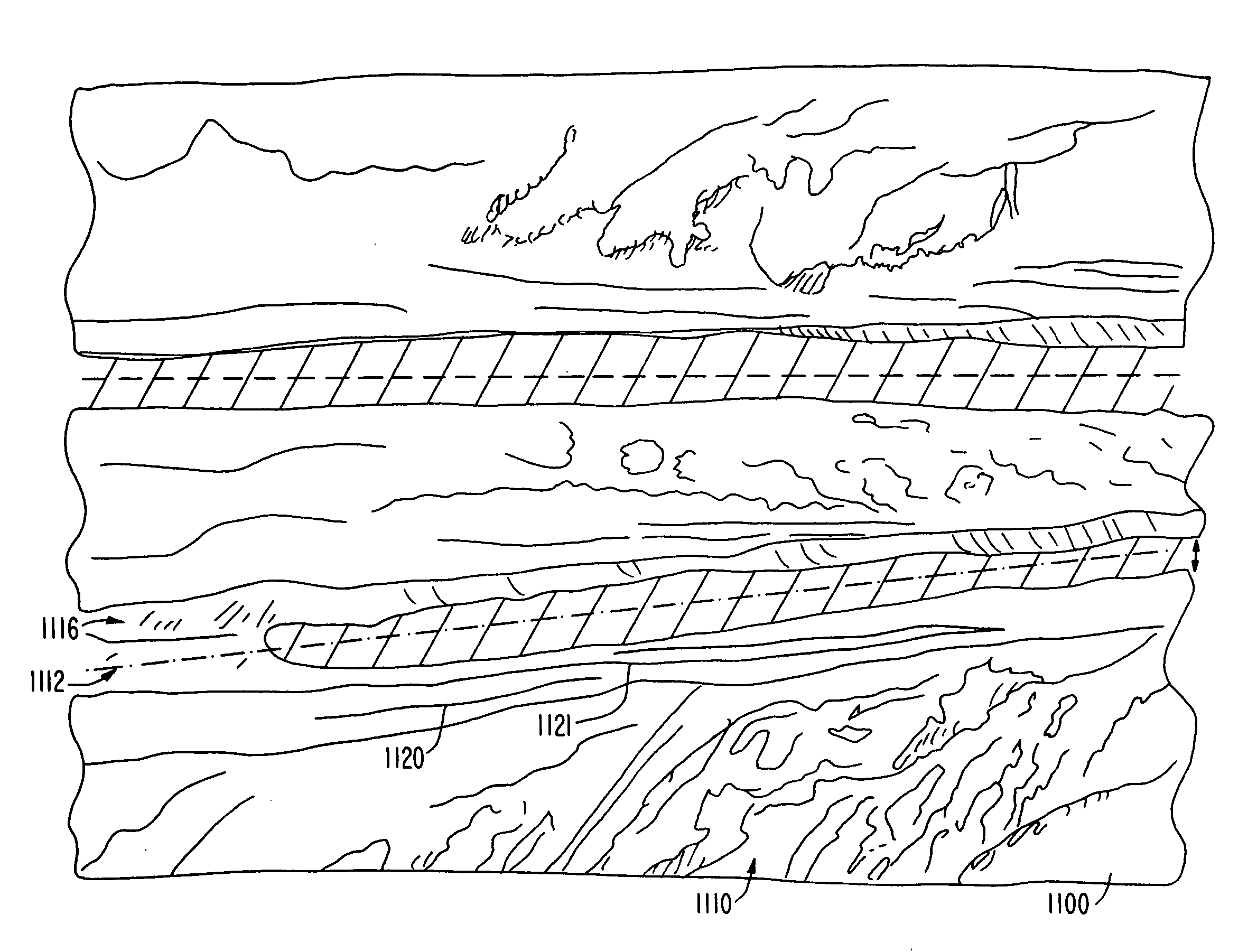
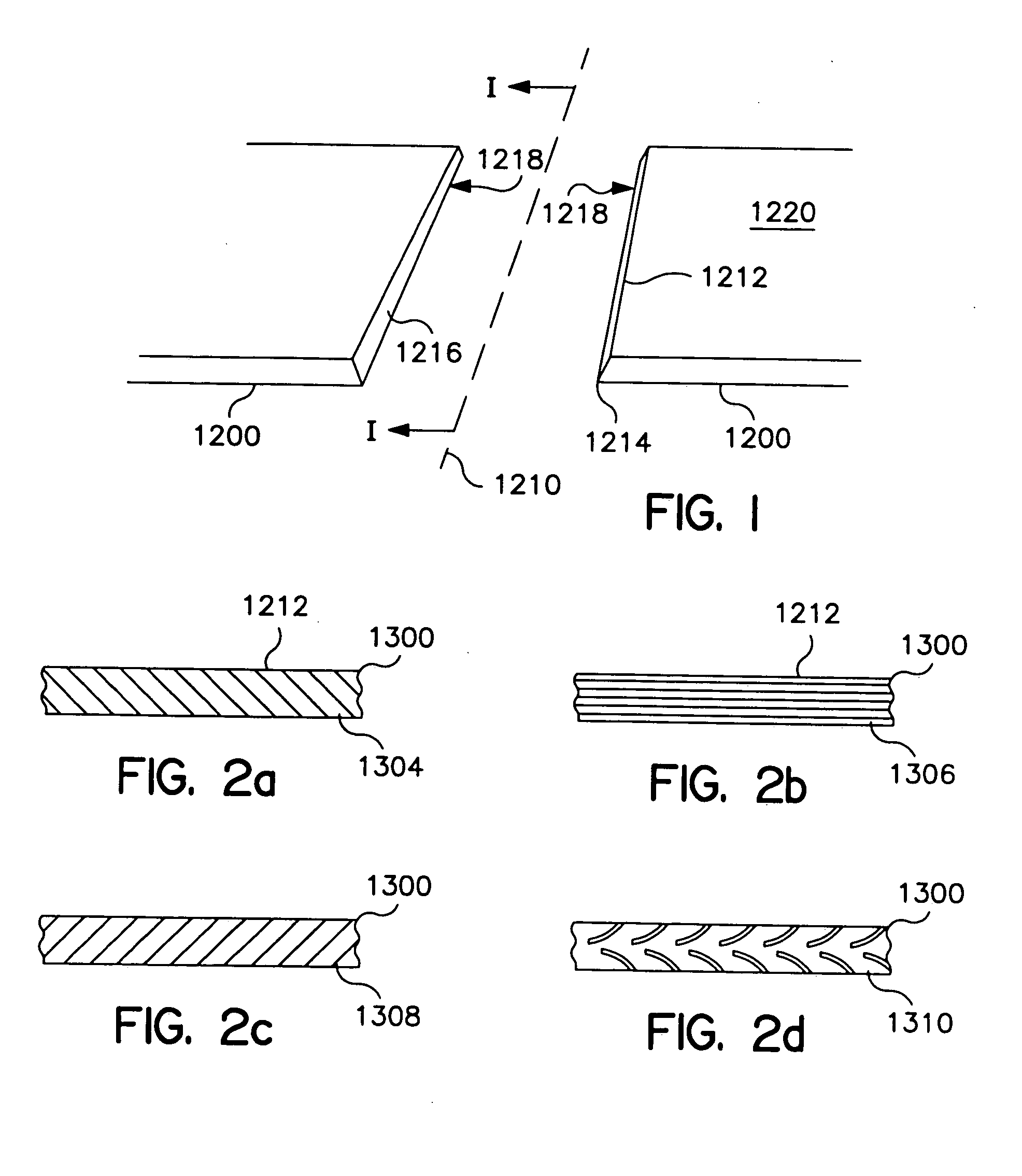
A method for cutting steel includes heating a portion of the steel until it is molten, positioning a cutting torch to have a high angle of incidence relative to the molten steel, and blasting hgih pressure oxygen at the molten metal. The blast of high pressure oxygen further heats the molten metal and blows the molten metal away from the steel to create a cutting trench. The cutting torch is then moved generally parallel to the cutting method includes a cutting torch that emits a high pressure combustible gas and a high pressure combustion enhancing gas. The torch directs the high pressure gases at the steel so that the gases hit the steel at an acute angle of attack. An automated device propels the torch in the general direction of the desired cut. The resultant cut metal product has at least one edge with a grain pattern that is not perpendicular to the direction of cut.

Description

CROSS REFERENCE TO RELATED APPLICATIONS [0001] This application is an application filed under 35 U.S.C. § 111(a) claiming benefit pursuant to 35 U.S.C. § 119(e) of the filing date of the Provisional Application No. 60 / 162,205 filed Oct. 29, 1999, pursuant to 35 U.S.C. § 111(b).BACKGROUND OF THE INVENTION [0002] 1. Field of the Invention [0003] The present invention is generally directed to new methods and machines for cutting metals, such as steel. More specifically, the present invention is directed to a process and apparatus by which steel is quickly cut so as to increase production capacity for steel fabrication, ship building, ship repair and heavy equipment production. [0004] 2. Background of the Invention [0005] The traditional method of metal cutting involves the use of cutting torches that use oxygen and acetylene gases. The cutting torch operator sets the oxygen gas pressure level to about 40 to 60 pounds per square inch and sets the acetylene gas pressure level to about 8 ...

Claims


Application Information

Patent Timeline
Patent Type & Authority Applications(United States)
IPC IPC(8): B23K7/00B23K7/10B23K37/02
CPCB23K7/002B23K7/003B23K7/004B23K7/008B23K7/10B23K7/102Y10T428/12229B23K37/0258B23K37/0408B23K2201/18B23K2203/04Y10T428/12389B23K37/0235B23K2101/18B23K2103/04
Inventor PASULKA, MATTHEW P.
Owner PASULKA MATTHEW P
Learn More