
Controllable amplifier and the use thereof

a technology of controllable amplifiers and amplifiers, applied in amplifier combinations, amplifier control devices, amplifiers, etc., to achieve the effect of reducing the operating current through the amplifier transistor, reducing the signal-to-noise ratio (snr) and reducing the cost and area

Inactive Publication Date: 2006-09-14
INTEL MOBILE COMM GMBH
View PDF10 Cites 17 Cited by
  • Summary
  • Abstract
  • Description
  • Claims
  • Application Information

AI Technical Summary

Benefits of technology

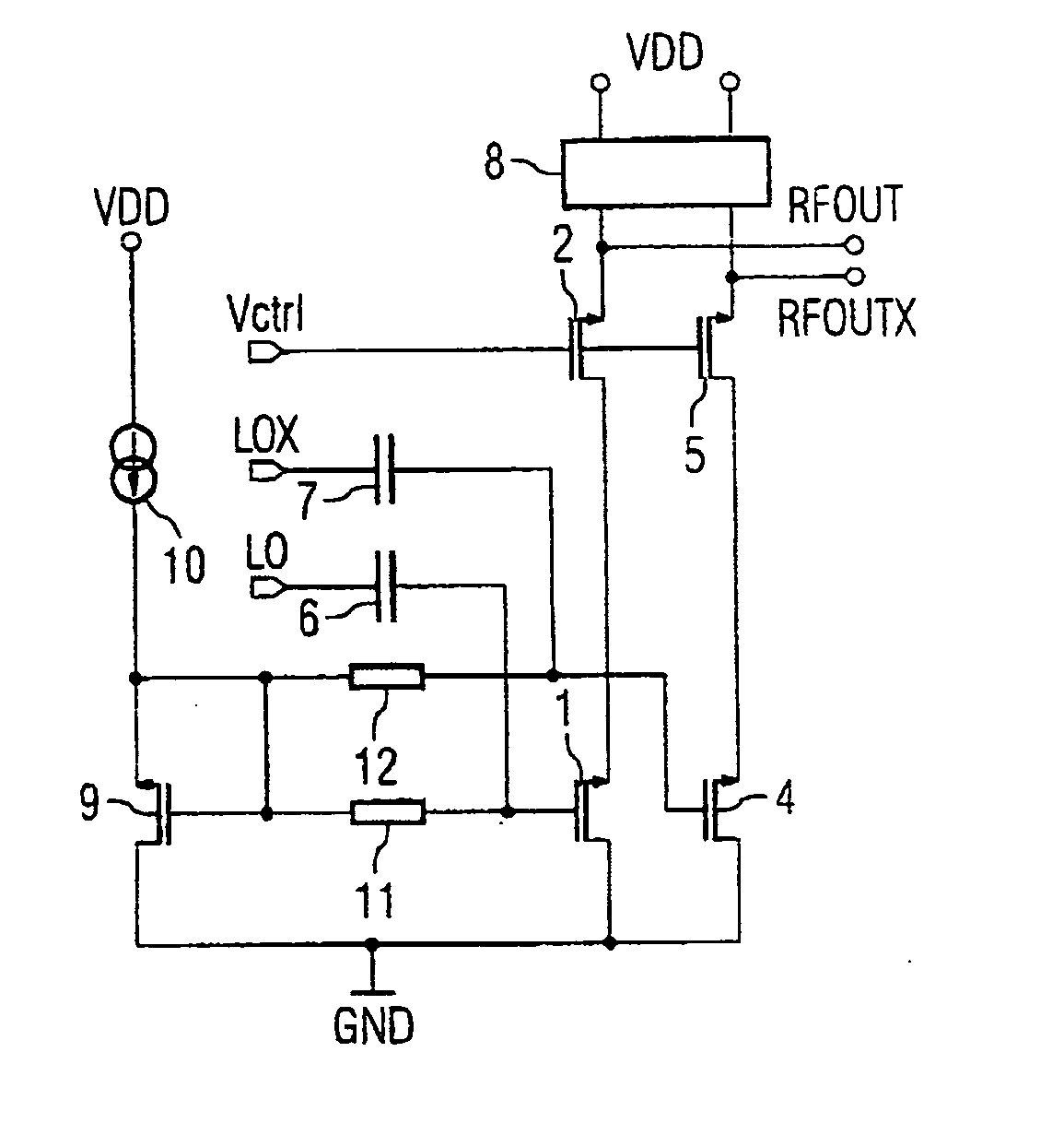
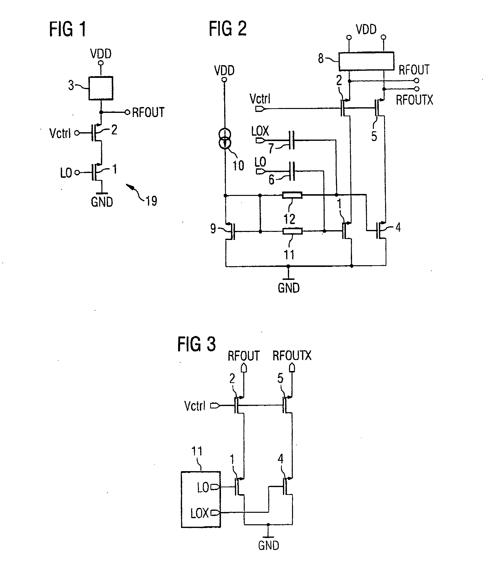
[0016] In the case of the proposed controllable amplifier, the drain / source resistance of the cascode transistor is large when the gate voltage is small. The voltage drop across the transistor reduces the drain / source voltage of the amplifier transistor and the output current of the amplified signal. The transistors (particularly the cascode transistor) are operated in the linear region in such a manner that the output power of the amplifier can be controlled over a wide dynamic range without distortion occurring in this case.
[0017] The proposed amplifier arrangement can be implemented with a small number of components. The cascode transistor which controls the gain does not generate substantial additional noise, with the result that the signal-to-noise ratio (SNR) is typically large. This makes it possible, with additional advantage, to dispense with a cost-intensive and area-intensive surface acoustic wave filter.
[0018] The operating current through the amplifier transistor is reduced in proportion to the signal current. The proposed circuit thus operates in such a manner that it can save substantial amounts of power. This also applies when only a low output power is required.
[0032] When the gate voltage is small, the drain / source resistance of the two cascode transistors is large. The voltage drop across these transistors reduces the drain / source voltage of the amplifier transistors and the signal output current. The transistors are operated in the linear region in such a manner that the output power can be controlled over a wide dynamic range without undesirable distortion occurring in this case. Even when using differential circuit technology, the amplifier can be implemented with a relatively simple design and, in particular, with a small number of components. Since the cascode transistors which control the gain do not generate additional noise, the signal-to-noise ratio is large. It is possible to dispense with a cost-intensive and area-intensive surface acoustic wave filter between the output of the amplifier and an RF output, for example an antenna. Since the operating current through the two amplifier transistors is reduced in proportion to the signal current of the signal to be amplified, the circuit operates in such a manner that it saves a lot of power, even when the output power is low.
[0036] The regulating circuit can be used to improve stability. This regulator arrangement can be employed when only a low output power is to be supplied, particularly in combination with the embodiment of the amplifier transistor as part of a current mirror.

Problems solved by technology

The characteristic variables of a VGA are not only the output power which can be achieved but also undesirable intermodulation, the noise properties and the power consumption, the latter in portable applications, in particular.

Method used


Image

  • Controllable amplifier and the use thereof
  • Controllable amplifier and the use thereof
  • Controllable amplifier and the use thereof

Examples


Embodiment Construction

[0050] One or more aspects and / or embodiments of the present invention are described with reference to the drawings, wherein like reference numerals are generally utilized to refer to like elements throughout, and wherein the various structures are not necessarily drawn to scale. In the following description, for purposes of explanation, numerous specific details are set forth in order to provide a thorough understanding of one or more aspects of the present invention. It may be evident, however, to one skilled in the art that one or more aspects of the present invention may be practiced with a lesser degree of these specific details. In other instances, known structures and devices are shown in block diagram form in order to facilitate describing one or more aspects of the present invention.

[0051]FIG. 1 shows a controllable amplifier having an input LO for supplying a radiofrequency input signal and having an output RFOUT at which an output signal which is derived from the radiofr...


PUM


Abstract

A controllable amplifier amplifies a radiofrequency input signal on the basis of a control signal. A current path is formed between a supply potential connection and a reference potential connection. The current path includes an amplifier transistor and a cascode transistor, the cascode transistor being connected to the input for supplying the control signal. The output power of the amplifier is controlled using the cascode transistor, as a result of which a low power consumption is achieved in conjunction with good noise properties.

Description

REFERENCE TO RELATED APPLICATIONS [0001] This application claims the benefit of the priority date of German application DE 10 2005 008 372.2, filed on Feb. 23, 2005, the contents of which are herein incorporated by reference in their entirety. FIELD OF THE INVENTION [0002] The present invention relates to a controllable amplifier, to a regulator arrangement having the controllable amplifier and to the use of a controllable amplifier. BACKGROUND OF THE INVENTION [0003] Controllable amplifiers are used, for example, in mobile radio technology. There, the output power of a transmitter in systems having linear modulation methods is controlled or regulated using the input power of the power output stage. Linear modulation methods are used, for example, in the UMTS (Universal Mobile Telecommunications System) and GSM / EDGE (Global System for Mobile Communication / Enhanced Data Rate for GSM Evolution) mobile radio systems. [0004] In order to avoid sudden changes in the gain, it is desirable ...

Claims


Application Information

Patent Timeline
IPC IPC(8): H03F3/45
CPCH03F1/223H03F1/26H03F3/195H03F3/245H03F3/45188H03F3/45201H03F2200/372H03F2200/451H03F2200/453H03F2200/456H03F2203/45024H03F2203/45052H03F2203/45311H03F2203/45398H03F2203/45544H03G1/0029H03G1/007
Inventor SIMON, MARTIN
Owner INTEL MOBILE COMM GMBH
Learn More