Heating systems

Active Publication Date: 2006-08-24
NGK INSULATORS LTD
View PDF4 Cites 25 Cited by
  • Summary
  • Abstract
  • Description
  • Claims
  • Application Information

AI Technical Summary

Benefits of technology

[0009] The inventors have tried to produce a tubular supporting member made of a corrosion resistant metal and to fix it to a ceramic heater and studied appropriate design for providing uniform temperature distribution on the heating face. The manufacturing cost of tubular supporting member is low, and the joining can be easily carried out with a mechanical method. Further, it is possible to remove the supporting member from the ceramic heater and reuse it, and relatively easy to change the design.
[0011] An object of the present invention is to provide a heating system having a ceramic heater and a supporting member supporting the back face of the heater, so that the cost of the supporting member can be reduced, the design change of the system can be made easier, and excellent flatness of the heating face on use can be maintained.
[0014] Based on the above discovery, the inventors have tried to provide a heat insulating plate between the back face of the heater and the supporting member. It has been successfully prevented a temperature increase of the part of the supporting member contacting the heat insulating plate and the deformation due to creep of the supporting member, so that the deterioration of the flatness and inclination of the heating face of the heater can be prevented.

Problems solved by technology

The tubular supporting member made of a heat resistant and dense ceramics has a high manufacturing cost, and the joining and firing of the supporting member to a ceramic heater is difficult.
The cost for the joining is also high.
It is thus impossible to remove the supporting member from the heater and to reuse the once joined supporting member.
Further, when the design of the ceramic supporting member is changed, simulation of the effects of the design change on the temperature distribution on the heating face is difficult, so that the design change requires a substantial time and troublesome work.
When a ceramic heater is fixed to the tubular supporting member made of a metal and the temperature on the heating face of the heater is raised to about 450° C., however, the flatness of the heating face may be deteriorated.
When the flatness of the heating face is deteriorated, the flatness of a semiconductor wafer mounted on the heating face is deteriorated, so that there is a risk that the ceramic heater is required to be replaced.

Method used


Image

  • Heating systems
  • Heating systems
  • Heating systems

Examples


example 1

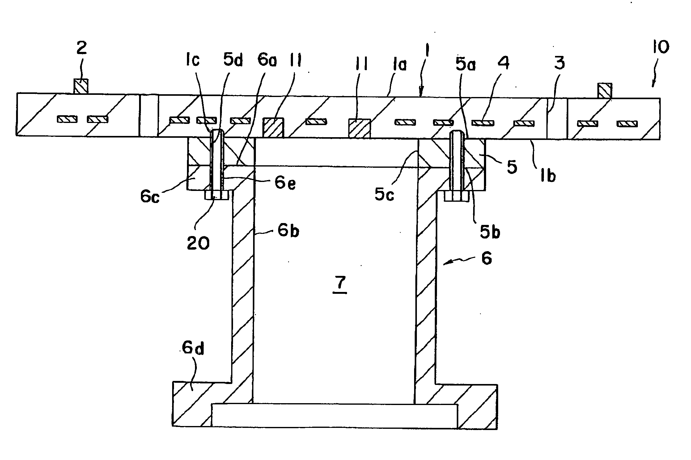
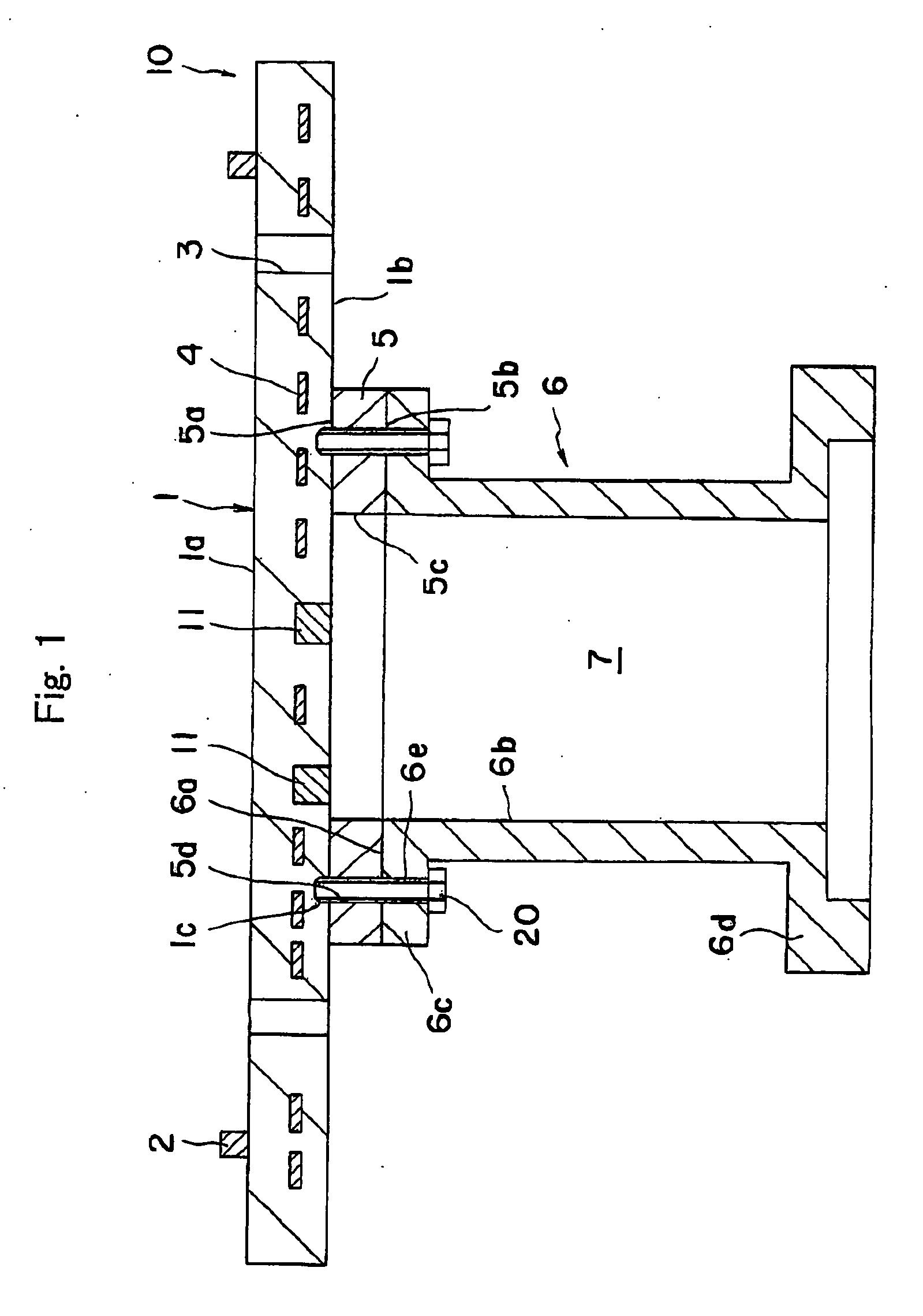
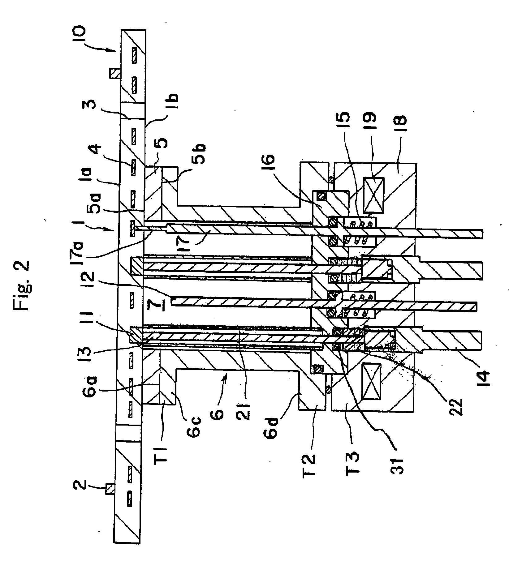
[0056] A heating system having a construction shown in FIGS. 1 and 2 was produced. The ceramic substrate 1 was made of an aluminum nitride sintered body, in which a molybdenum coil was embedded as the heat generator. Pins 2 for mounting wafer were formed of alumina. The thickness of the substrate 1 was 10 mm and the diameter φ was 320 mm. The heat insulating plate 5 was made of alumina, the thickness of the heat insulating plate 5 was 8 mm and the diameter φ was 80 mm. The tubular supporting member 6 was formed of aluminum alloy, the insulating tube 21 was formed of alumina, and the rod 13 for power supply was formed of nickel. The cooling shaft 18 was formed of aluminum alloy. Nitrogen gas was flown from the tip end of the purging tube 12, while the cooling flange 19 was cooled with flowing water. The heat insulating plate 5, flange portion 6c, and substrate 1 were fastened with a screw 20 made of Inconel.

[0057] Using the thus produced heating system, the pressure in the chamber w...

example 2

[0060] A heating system having a construction shown in FIGS. 3 to 5 was produced. The ceramic substrate 1 was made of an aluminum nitride sintered body, in which a molybdenum coil was embedded as the heat generator. Pins 2 for mounting wafer were formed of alumina. The thickness of the substrate 1 was 10 mm and the diameter φ was 320 mm. The heat insulating plate 5 was made of alumina, the thickness of the heat insulating plate 5 was 8 mm and the diameter φ was 80 mm. The tubular supporting member 6 was formed of aluminum alloy, the insulating tube 21 was formed of alumina, and the rod 13 for power supply was formed of nickel. The cooling shaft 18 was formed of aluminum alloy. Nitrogen gas was flown from the tip end of the purging tube 12, while the cooling flange 19 was cooled with flowing water. The heat insulating plate 5, flange portion 6c, and substrate 1 were fastened with a bolt 20 made of Inconel. The elastic body 21 was composed of a coil spring made of SUS and a washer mad...


PUM

PropertyMeasurementUnit
Electrical resistanceaaaaaaaaaa
Elasticityaaaaaaaaaa
aaaaaaaaaa

Abstract

An object of the present invention is to provide a heating system having a ceramic heater and a supporting member supporting the back face of the heater, so that the cost of the supporting member can be reduced, the design change of the heater is made easier and excellent flatness of the heating face on use can be maintained. The heating system has a ceramic substrate 1 having a heating face 1a and a back face 1b, a heating means 4 for generating heat from the heating face 1a of the substrate 1, a metal supporting member 6 supporting The back face 1b of the substrate 1, and a heat insulating plate 5 provided between the back face 1b of the substrate 1 and the supporting member 6.

Description

BACKGROUND OF THE INVENTION [0001] 1. Field of the Invention [0002] The invention relates to a heating system. [0003] 2. Related Art Statement [0004] In a system for producing semiconductors, a ceramic heater has been provided for heating a wafer so as to deposit a semiconductor thin film on the wafer from gaseous raw materials such as silane gas by means of thermal CVD or the like. A so called two-zone heater is known as such ceramic heater. Such two-zone heater has a ceramic substrate and inner and outer resistance heat generators made of a metal of a high melting point embedded in the substrate. Separate power supply terminals are connected to the respective heat generators so that electric power is applied independently on the respective generators. The inner and outer heat generators can be thus independently controlled. [0005] According to JP-A 5-326112, a resistance heat generator of a ceramic heater is constituted by plural circuit patterns each made of a high melting point ...

Claims


Application Information

Patent Timeline
IPC IPC(8): H05B3/68
CPCH01L21/67103H05B3/143
Inventor GOTO, YOSHINOBUTSURUTA, HIDEYOSHI
Owner NGK INSULATORS LTD
Why Eureka
Try Eureka