Method of pad printing in the manufacture of capacitors
a capacitor and pad printing technology, applied in the field of device production, to achieve the effect of improving adhesion, sustaining long-term performance, and increasing yield
- Summary
- Abstract
- Description
- Claims
- Application Information
AI Technical Summary
Benefits of technology
Problems solved by technology
Method used
Image
Examples
example i
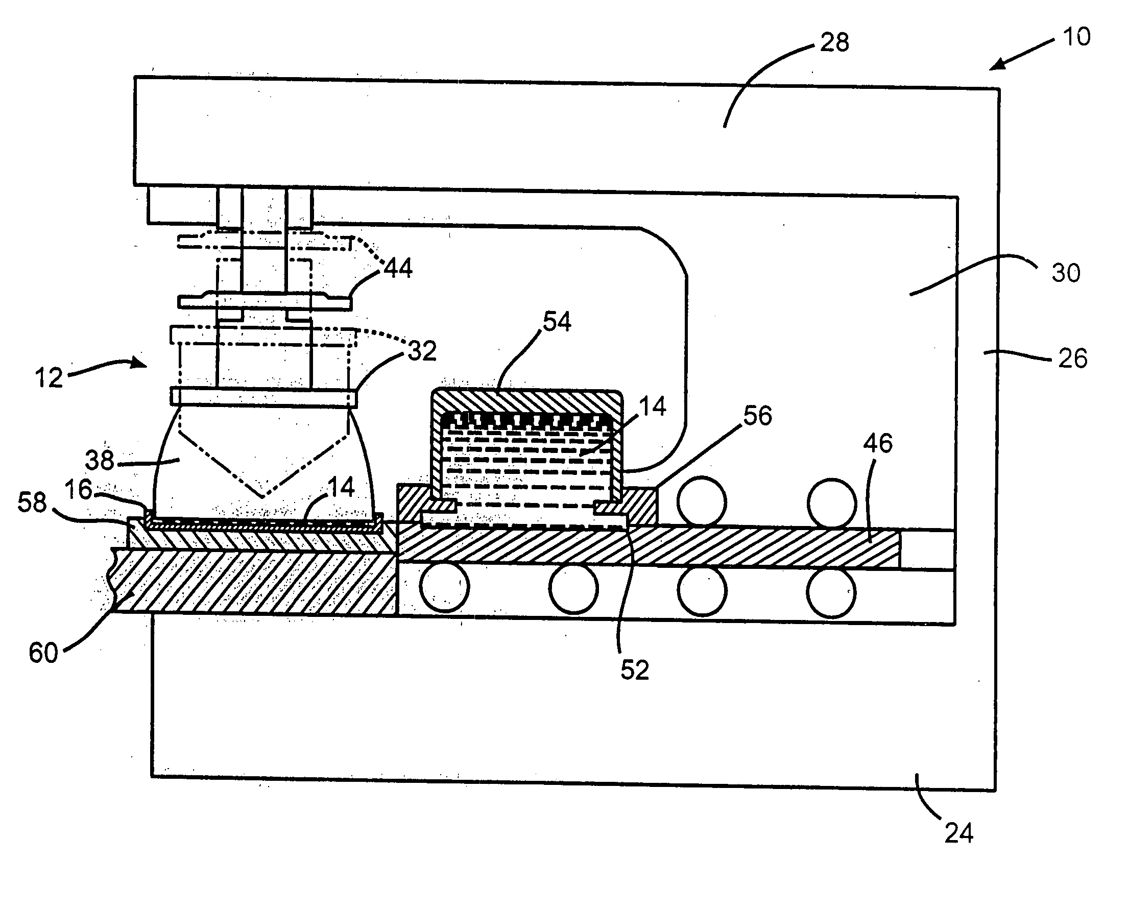
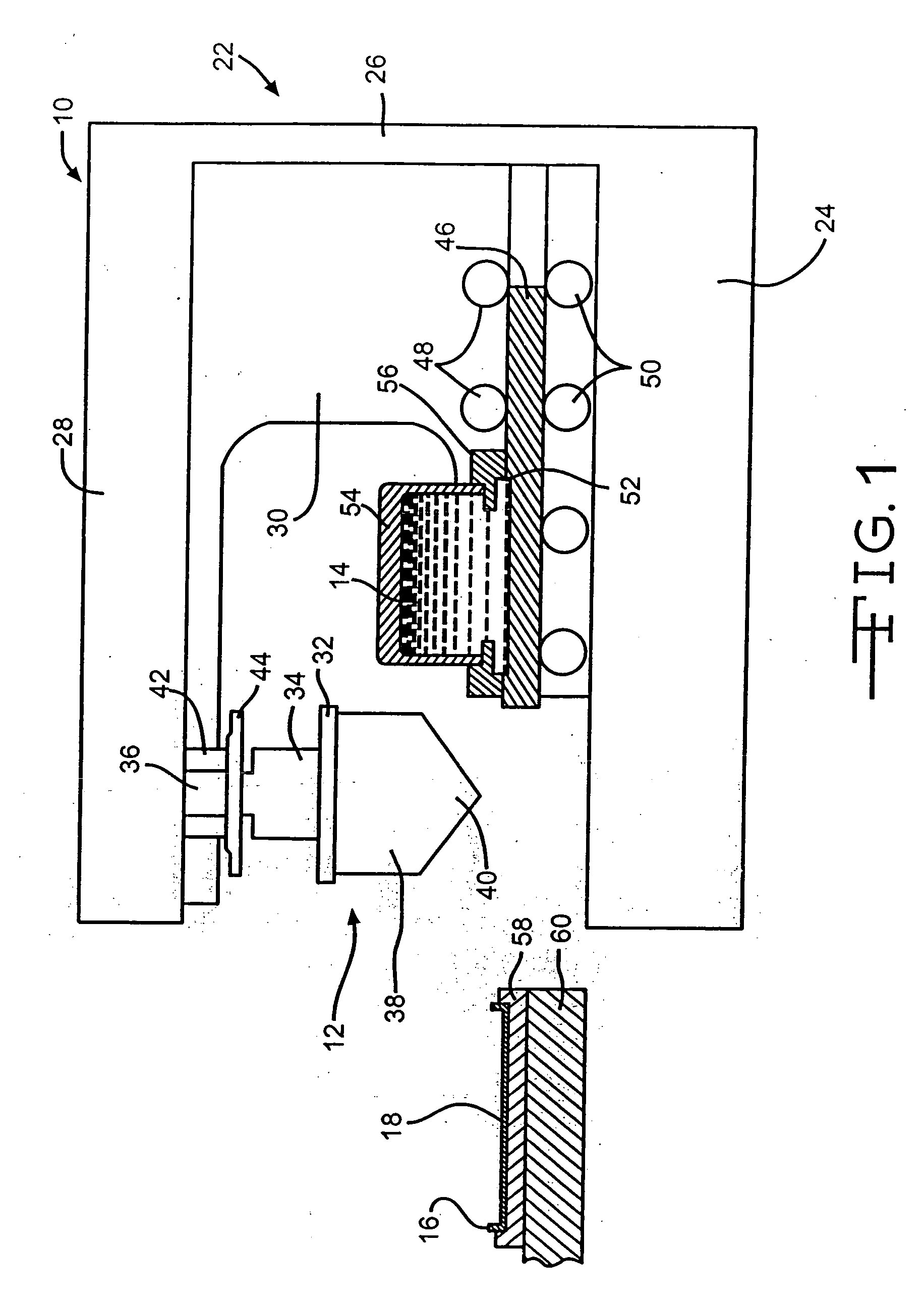
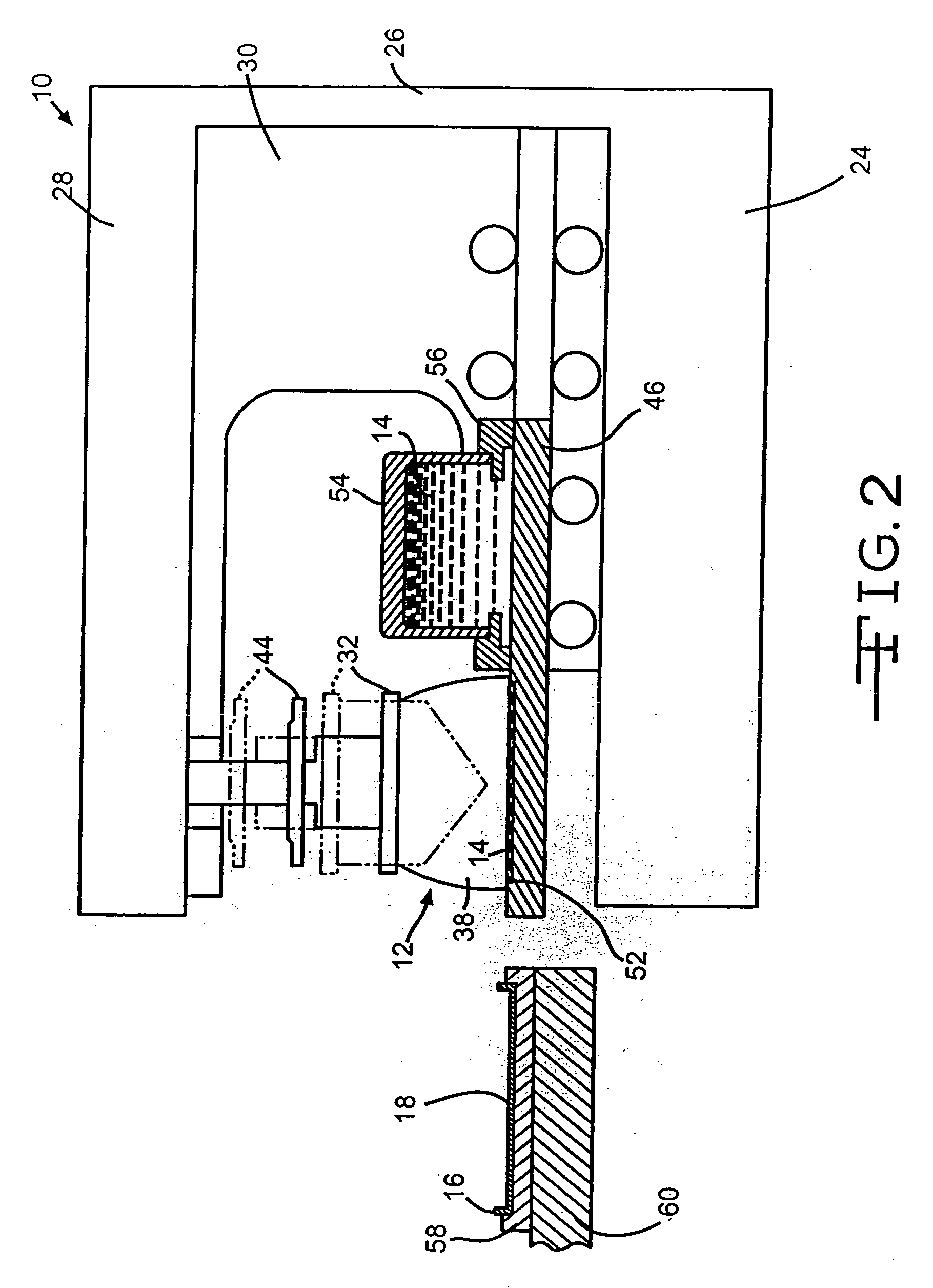
[0109] One hundred fifty titanium substrates as casing portions similar to substrate 16 in the drawing figures were coated with an active ruthenium dioxide material by a closed inkwell pad printing process according to the present invention. The ink was a suspension of ruthenium dioxide and polyvinyl butyral binder in a solvent mixture of terpineol and butyl carbitol. The coated substrates were then divided into three groups of fifty substrates apiece. The first group was heated to a maximum temperature of 200° C., the second group was heated to 300° C. and the third group was heated to 400° C.
[0110] Test capacitors were then constructed from the processed cathode substrates. Each capacitor comprised a pressed and anodized tantalum powder anode positioned between two mating casing portions containing ruthenium oxide cathode coatings heated to the same final temperature. An electrolyte was filed into the sealed casing to contact the anode and the cathode, which were segregated from ...
example ii
[0112]FIG. 29 is a graph showing the weight loss versus heating temperature for a poly(propylene carbonate) binder. Curve 410 is constructed from the binder heated in air, curve 412 is from the binder heated in hydrogen, curve 414 is from the binder heated in a vacuum (1 Torr) and curve 416 is from the binder heated in nitrogen. It can be seen that substantially all of the weight loss occurs prior to heating at about 300° C.
example iii
[0113] Substrates pad printed in a similar as those used to construct the capacitors of the three groups used in Example I were heated to 250° C., 300° C., 350° C. and 450° C., respectively. The substrates were then subjected to an x-ray diffraction (XRD) analysis. The results are shown in FIG. 30. This XRD graph is indicative of the crystallinity of the ruthenium oxide active material. The higher peaks indicate a more crystalline material. It is clear that the ruthenium oxide material heated to a final temperature of 250° C. is not as crystalline as the other materials heated to higher temperatures.
PUM
| Property | Measurement | Unit |
|---|---|---|
| temperature | aaaaa | aaaaa |
| diameter | aaaaa | aaaaa |
| pore size | aaaaa | aaaaa |
Abstract
Description
Claims
Application Information
 - R&D
- Intellectual Property
- Life Sciences
- Materials
- Tech Scout
- Unparalleled Data Quality
- Higher Quality Content
- 60% Fewer Hallucinations
Browse by: Latest US Patents, China's latest patents, Technical Efficacy Thesaurus, Application Domain, Technology Topic, Popular Technical Reports.
© 2025 PatSnap. All rights reserved.Legal|Privacy policy|Modern Slavery Act Transparency Statement|Sitemap|About US| Contact US: help@patsnap.com


