Etching method

a technology of etching and etching plate, which is applied in the direction of fluid pressure measurement, instruments, vacuum gauges, etc., can solve the problems of poor patterning, inaccurate etching, and inability to obtain accurate patterns, etc., and achieve satisfactory selectivity, accurate etching, and good shape patterns

Inactive Publication Date: 2006-06-08
TOKYO ELECTRON LTD
View PDF5 Cites 2 Cited by
  • Summary
  • Abstract
  • Description
  • Claims
  • Application Information

AI Technical Summary

Benefits of technology

[0010] The present invention has been made in view of the above difficulties. An object of the present invention is to provide a method of etching a lower layer film of an organic material, using an upper layer film of an Si-containing organic material as a mask, in which the lower layer film can be accurately etched at a satisfactory selectivity, so that a well-shaped pattern can be realized.
[0011] With a view to achieving this object, the inventors of the present invention have conducted research and found that, when a mixed gas containing an NH3 gas and an O2 gas is used for etching the lower layer film, a CD shift value can be controlled at a desired value, so that etching can be accurately performed to provide a well-shaped pattern, while maintaining a satisfactory selectivity.
[0015] According to the present invention, the O2 gas can more effectively work in the etching process, and a satisfactory CD shift value can be obtained. In addition, a generation of etching residue can be restrained. In this case, it is preferable that the flow ratio of the O2 gas to the NH3 gas is from 5 to 10%.

Problems solved by technology

However, when a thickness of a resist film is reduced so as to form a finer pattern, a sufficient etching selectivity of a film to be etched cannot be taken relative to the resist film, which results in poor patterning.
However, when a film is etched by using the O2-based gas, etching cannot be accurately performed, and thus an accurate pattern cannot be obtained.
However, a use of the mixed gas containing the H2 gas and the N2 gas lowers an etching selectivity of the lower layer resist relative to the upper layer resist.
Thus, a thickness of the upper layer resist is unavoidably decreased when the lower layer resist is etched, which impairs the advantages of the double-layered resist.

Method used


Image

  • Etching method
  • Etching method
  • Etching method

Examples


Embodiment Construction

[0026] An embodiment of the present invention will be described in detail below, with reference to the accompanying drawings.

[0027] [Etching System]

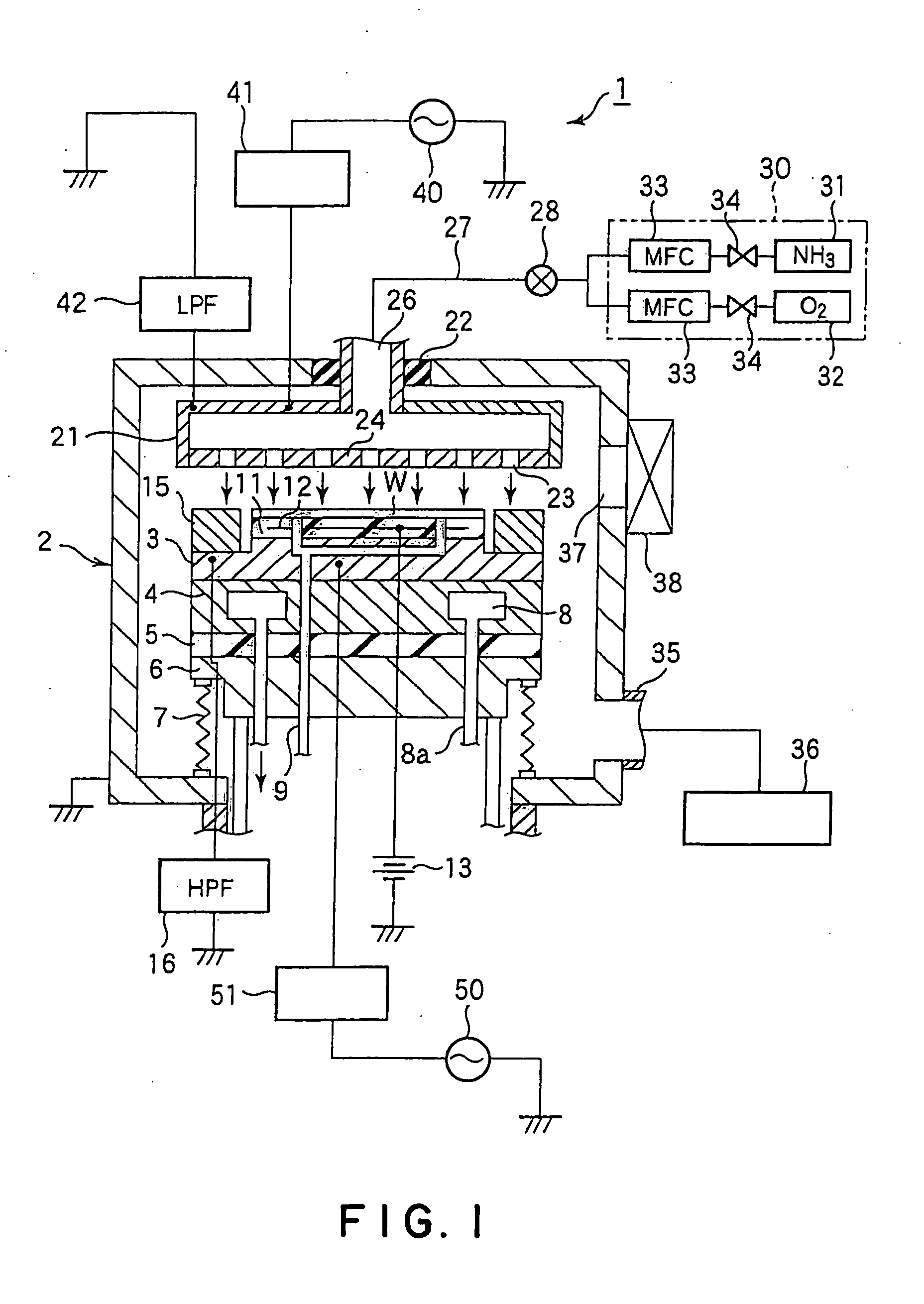
[0028]FIG. 1 is a sectional view schematically showing a plasma etching system for carrying out the present invention. The plasma etching system 1 shown in FIG. 1 is of a capacitively-coupled, parallel flat-plate type, and includes a pair of vertically opposed electrodes arranged in parallel with each other. A power source for generating a plasma is connected to one of the electrodes.

[0029] The plasma etching system 1 includes a cylindrical processing vessel 2 made of aluminum having its surface thermally sprayed by ceramics. The processing vessel 2 is protectively grounded. The processing vessel 2 is provided with a susceptor 3 supported by a support member 4. The susceptor 3 serves as a lower electrode. A semiconductor wafer W is horizontally mounted on the susceptor 3. The wafer W is made of Si, for example, and has on its surface a...


PUM

PropertyMeasurementUnit
pressureaaaaaaaaaa
pressureaaaaaaaaaa
pressureaaaaaaaaaa

Abstract

The present invention is a method of etching a lower layer film (64) of an organic material formed on a surface layer (61) of a substrate, using an upper layer film (63) of an Si-containing organic material as a mask. A mixed gas containing an NH3 gas and an O2 gas is supplied into the processing vessel as an etching gas, so as to perform etching by a plasma of the etching gas. When the etching gas is supplied into the processing vessel, a CD shift value of etching can be controlled by adjusting a flow ratio of O2 gas to the NH3 gas. Specifically, a satisfactory CD shift value can be obtained when the flow ratio is from 0.5 to 20%, and preferably, 5 to 10%.

Description

TECHNICAL FIELD [0001] The present invention relates to a method of etching, for example, a lower layer resist of a double-layered resist. More particularly, it pertains to a method of plasma-etching a lower layer film of an organic material formed on a substrate, using an upper layer film of an Si (silicon)—containing organic material as a mask. BACKGROUND ART [0002] A highly integrated semiconductor device has been desired in recent years, and thus there is a need for forming a finer pattern. In a photolithography process, in order to obtain a higher resolution for a finer pattern, it is necessary to reduce a thickness of a resist film formed on a semiconductor wafer, which is used when a pattern is formed thereon by dry-etching. [0003] However, when a thickness of a resist film is reduced so as to form a finer pattern, a sufficient etching selectivity of a film to be etched cannot be taken relative to the resist film, which results in poor patterning. [0004] In order to avoid thi...

Claims


Application Information

Patent Timeline
Patent Type & Authority Applications(United States)
IPC IPC(8): G01L21/30C23F1/00H01L21/3065H01L21/311
CPCH01L21/31144H01L21/31138H01L21/3065
Inventor OGAWA, SHUHEIINAZAWA, KOICHIRO
Owner TOKYO ELECTRON LTD
Why Eureka
Try Eureka