Mold for fabricating barrier rib and method of fabricating two-layered barrier rib using same

Inactive Publication Date: 2006-05-25
SAMSUNG DISPLAY CO LTD
View PDF27 Cites 16 Cited by
  • Summary
  • Abstract
  • Description
  • Claims
  • Application Information

AI Technical Summary

Benefits of technology

[0012] The present inventors have conducted extensive studies into the solutions of problems occurring in the prior art, resulting in the finding that, when employing a mold for fabricating a barrier rib, which includes a plurality of tapered protruding parts and a plurality of recessed parts, and an embossing process according to the present invention, it is possible to relatively simply fabricate a two-layered barrier rib for inkjet applications, which includes an ink-philic layer and an ink-phobic layer, through a single embossing process, thereby accomplishing various aspects of the present invention.
[0016] In order to accomplish the above objects, according to an aspect of the present invention, there is provided a mold for fabricating a barrier rib. The mold comprises a plurality of protruding parts and a plurality of recessed parts. The protruding parts and the recessed parts are arranged at regular intervals, and the recessed parts have a shape corresponding to embossed ink barrier portions to be fabricated. The protruding parts have shapes corresponding to depressed portions of the barrier rib to be fabricated, protrude adjacent to the recessed parts, and are tapered, therefore each protruding part of the mold has a triangular loop-like shape (See FIGS. 3a and 3b). This tapered shape of the mold makes the process simple as shown in later. Accordingly, the surface of recessed part of embossed barrier rib structure is not flat rather grooved, however, it is almost flat as long as the apex angle of the top of the protruding part is not much less than 180°.

Problems solved by technology

However, if the barrier rib is fabricated through the above methods, undesirably, a plurality of complicated coatings, mask aligning steps and exposure processes must be carried out.
However, all of the above methods need at least one additional photolithography process which incurs a high cost, particularly because of a surface treatment or the use of costly devices and fine chemicals in great quantities.

Method used


Image

  • Mold for fabricating barrier rib and method of fabricating two-layered barrier rib using same
  • Mold for fabricating barrier rib and method of fabricating two-layered barrier rib using same
  • Mold for fabricating barrier rib and method of fabricating two-layered barrier rib using same

Examples


example 1

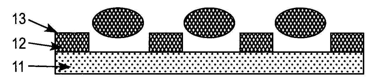
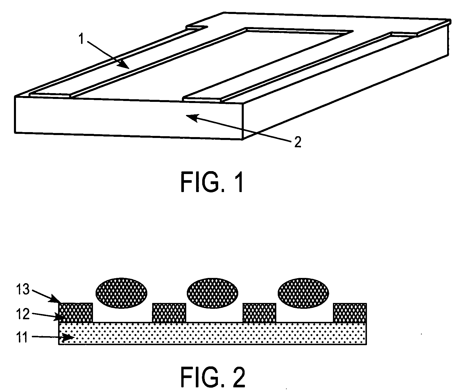
Fabrication of a Two-Layered Barrier Rib for an Inkjet Printing Color Filter, which has a Hydrophilic Lower Layer and a Hydrophobic Upper Layer, Through a UV Embossing Process

[0054] A monomer mixture liquid of 70 wt % aliphatic urethane-acrylate telechelic oligomer (Ebecryl 284 manufactured by UCB, Inc.) and 30 wt % hexanediol diacrylate (HDDA manufactured by UCB, Inc.), which had viscosity of 10,000 mPa·sec, as a solvent-free hydrophilic UV-curable material, was mixed with 0.75 wt % bisacylphosphine oxide (BAPO) as a photoinitiator based on the total monomer mixture liquid, and the resulting mixture was applied on a glass substrate having a thickness of 0.7 mm at 500 rpm for 30 sec to form an ink-philic layer (lower layer) having a thickness of 8 μm. 2,2,3,3-tetrafluoropropyl methacrylate monomer (viscosity of 10 mPa·sec) as hydrophobic UV curable material, which contained 0.1 wt % solvent-free fluorine-based surfactant (FC-430 manufactured by 3M Co.) and 1.0 wt % BAPO, was blade ...

example 2

Fabrication of a Barrier Rib for an Inkjet Printing OLED, which has a Hydrophobic Lower Layer and a Hydrophilic Upper Layer, Through a UV / Hot Embossing Process

[0055] A surface of a mold was coated with a fluorine-based surfactant (Zonyl manufactured by DuPont, Inc.) and baked at 200□ so as to have a hydrophobic property. Poly(2,2,3,3-tetrafluoropropyl methacrylate) having a molecular weight of 100,000 (a glass transition temperature of about 66° C.) was dissolved in methylisobutylketone (MIBK) so as to have a concentration of 5 wt %, and applied on a glass substrate using a spin coater at a rotation rate of 2000 rpm to form a lower layer. 2-hydroxyethyl methacrylate oligomer, which was produced by dissolving Irgacure 184 and polymerizing it through UV polymerization until the viscosity was 1,000 mPa·sec, was applied thereon at a rotation rate of 2000 rpm. Subsequently, the mold for fabricating a barrier rib according to the present invention was brought into close contact with the ...

example 3

Fabrication of a Barrier Rib for an Inkjet Printing OLED, which has A Hydrophobic Lower Layer and a Hydrophilic Upper Layer, Through a UV Embossing Process

[0056] The surface of a mold was coated with a fluorine-based surfactant (Zonyl manufactured by DuPont, Inc.) and baked at 200° C. so as to have a hydrophobic property. ORMOCER B59 manufactured by Microresist Co., that is, hydrophobic organic / inorganic hybrid UV curable resin, was applied on a glass substrate using a spin coater at a rotation rate of 3000 rpm. 2-hydroxyethyl methacrylate (HEMA) monomer containing Irgacure 184 was applied thereon in drops of 1 ml using a pipette. Subsequently, the mold for fabricating a barrier rib according to the present invention was brought into close contact with the entire surface of an upper layer, embossing was conducted at room temperature and pressure of 5 kgf / cm2, the backside of the glass substrate was exposed to UV of 1 kW for 3 min using a UV exposing machine, and the mold was remove...


PUM


Abstract

The disclosed mold includes recessed parts which have a shape corresponding to embossed portions of the barrier rib to be fabricated, and protruding parts which have a shape corresponding to depressed portions of the barrier rib to be fabricated, protrude adjacent to the recessed parts, and are tapered. The protruding parts and the recessed parts are arranged at regular intervals. It is possible to simply fabricate the two-layered barrier rib for inkjet application through a single embossing process at low cost using the mold for fabricating the barrier rib of the present invention.

Description

BACKGROUND OF THE INVENTION [0001] Priority is claimed to Application No. 2004-97649, filed in the Republic of Korea on Nov. 25, 2004, herein incorporated by reference. [0002] 1. Field of the Invention [0003] The present invention relates, in general, to a mold for fabricating a barrier rib and a method of fabricating a two-layered barrier rib using the same and, more particularly, to a mold for fabricating a barrier rib that includes a plurality of tapered protruding parts and recessed parts having a shape corresponding to embossed portions of the barrier rib, and a method of fabricating a two-layered barrier rib for inkjet application using the same through a low-cost simple process. [0004] 2. Description of the Related Art [0005] As shown in FIG. 1, a conventional barrier rib for display devices has a vertically and horizontally striped structure so as to discriminate RGB pixels on a transparent glass substrate 2. A space between the barrier ribs is empty and the adjacent surface...

Claims


Application Information

Patent Timeline
IPC IPC(8): H01J19/42H01J17/49H01J1/88
CPCG02F1/133512H01J9/242H01J2211/36
Inventor CHO, HAN SOLPARK, YONG YOUNGPARK, JOON YONGSON, YOUNG MOK
Owner SAMSUNG DISPLAY CO LTD
Why Eureka
Try Eureka