Separator, fuel cell device, and temperature control method for fuel cell device

Inactive Publication Date: 2006-05-18
SONY CORP
View PDF3 Cites 51 Cited by
  • Summary
  • Abstract
  • Description
  • Claims
  • Application Information

AI Technical Summary

Benefits of technology

[0012] Besides, in consideration of the above-mentioned problems, it is another object of the present invention provides in another embodiment a separator, a fuel cell device, and a temperature control method for a fuel cell device by which it is possible to enhance the efficiency of release of heat from a power generation unit and to reduce the size of a fuel cell.
[0048] According to the present invention in an embodiment, there is provided a temperature control method for a fuel cell device, for controlling the temperature of a fuel cell main body in which a power generation body and a separator for making electrical conduction between the power generation body and another power generation body are laminated, wherein the separator includes a separator main body portion making contact with the power generation bodies, and a thermal radiation portion projectingly provided at a side edge portion of the separator main body portion; the thickness of at least a part of an edge portion of the thermal radiation portion is set smaller than the thickness of a central portion of the thermal radiation portion; and a cooling fluid for cooling the fuel cell main body is made to flow in the circumference of the thermal radiation portion. According to such a temperature control method for a fuel cell device, the flow of the cooling fluid is not hindered, so that the cooling fluid is permitted to flow smoothly, and the cooling fluid with a sufficient heat capacity can constantly be taken into the space between the adjacent thermal radiation portions while discharging the cooling fluid having received heat at the time of power generation. Therefore, it is possible to sufficiently release heat from the fuel cell main body through the thermal radiation portions, and to perform stable power generation while suppressing the rise in temperature.

Problems solved by technology

Since the fuel cell generates electric power by the chemical reaction between hydrogen and oxygen, heat is generated due to the loss component arising from the electrochemical reaction, the electric resistances of the materials constituting the power generation unit and the like, leading to a rise in the temperature of the fuel cell main body in which the power generation cells are laminated.
The fuel cell main body is the power generation unit which substantially performs power generation, and the temperature rise in the power generation unit is unfavorable for the purpose of stable power generation.
For example, in a solid polymer type fuel cell having a power generation body composed of a solid polymer electrolyte membrane and electrodes sandwiching the solid polymer electrolyte membrane therebetween, the amount of moisture contained in the solid polymer electrolyte membrane may in some cases be reduced attendant on the temperature rise, resulting in the trouble called “dry-up”.
When power generation is conducted in the condition where temperature gradients are generation over the range from the central portion to the upper portion of the power generation unit and over the range from the central portion to the lower portion of the power generation unit, such troubles as the dry-up may be generated in the power generation cell higher in temperature than the other power generation cells, particularly in the power generation cell disposed in the vicinity of the center of the power generation unit, making it difficult to achieve stable power generation by the power generation unit.
Hei 10-162842, the technology of controlling the temperature of the power generation cells according to the positions of the power generation cells disposed in the power generation unit is not referred to, and it is difficult, in the case of the power generation unit having the stack structure, to improve the temperature gradients generated with respect to the lamination direction of the power generation bodies and the separator main body portions, and to perform power generation while keeping uniform the temperature of the power generation unit as a whole.
In the case of the fuel cell having a separator with such a heat pipe connected thereto, the structure of the fuel cell is necessarily complicated, which may cause a hindrance in reducing the size of the fuel cell.

Method used


Image

  • Separator, fuel cell device, and temperature control method for fuel cell device
  • Separator, fuel cell device, and temperature control method for fuel cell device
  • Separator, fuel cell device, and temperature control method for fuel cell device

Examples


Embodiment Construction

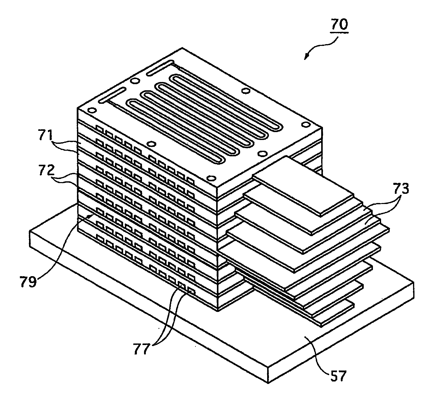
[0069] Now, the separator and the fuel cell device according to the present invention will be described below. The separator according to the present inventor has a characteristic feature in a thermal radiation portion, and, further, the fuel cell device including the separator according to the present invention, i.e., the fuel cell device with a power generation unit mounted therein is a fuel cell device capable of performing power generation while keeping uniform the temperature of the power generation unit by utilizing the characteristic feature of the thermal radiation portion.

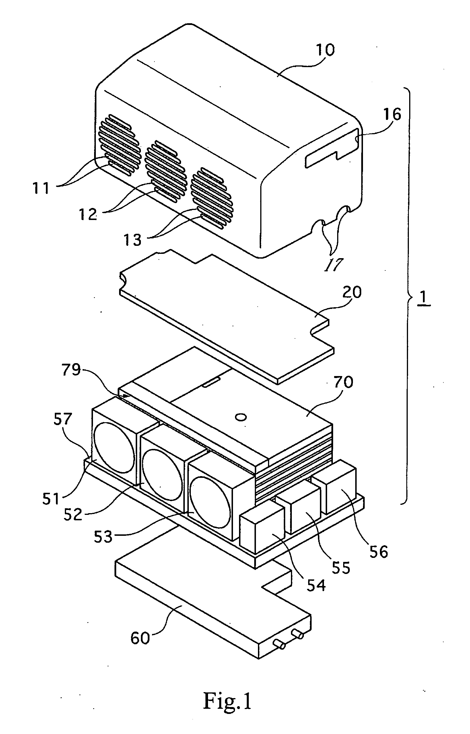
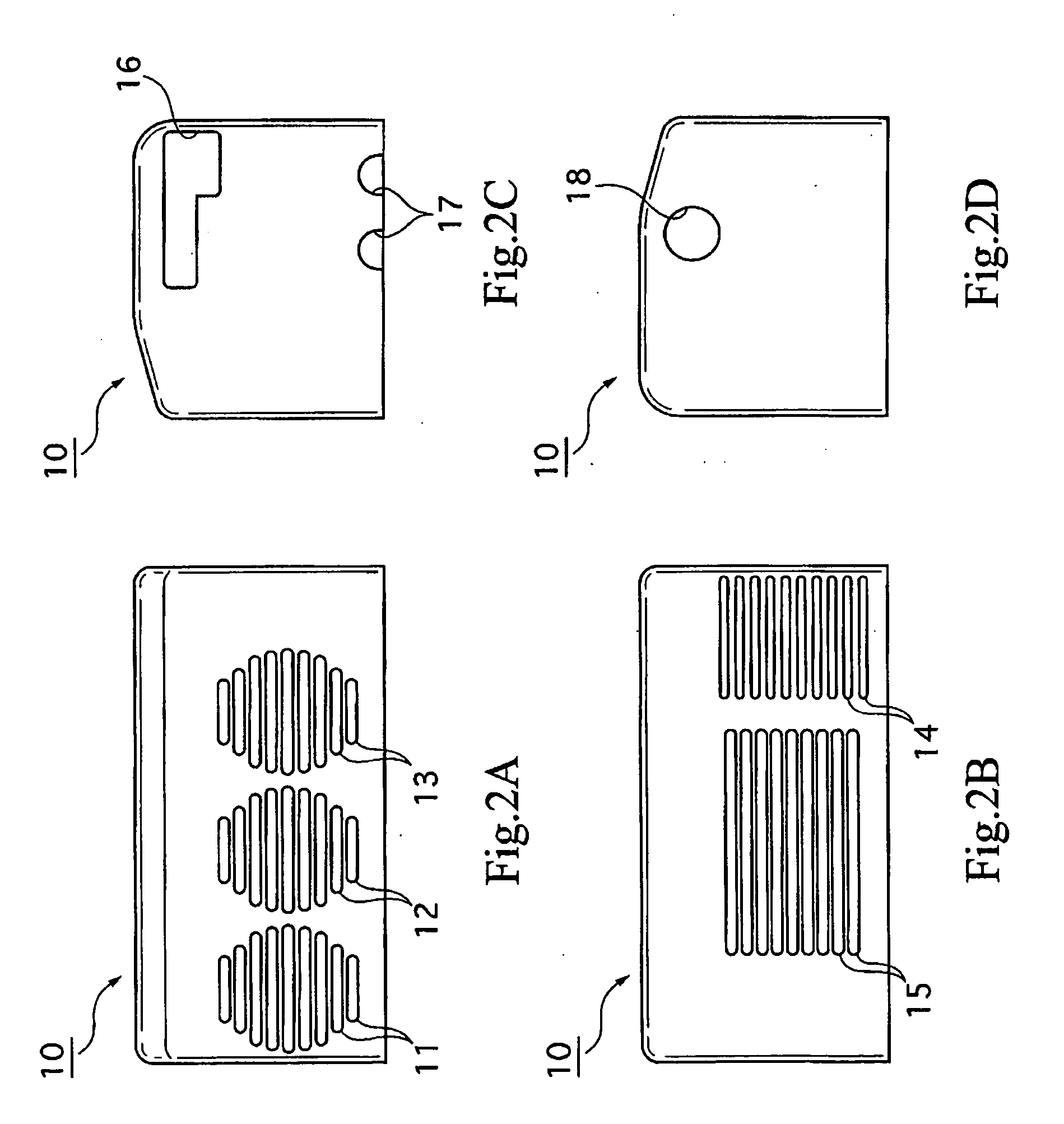
[0070] First, the configurations of the separator and the fuel cell device according to the present invention will be described referring to FIGS. 1 to 7. As shown in FIG. 1, the fuel cell device 1 includes a casing 10, a control substrate 20, a power generation unit 70, a cooling fan 51, air supply fans 52 and 53, a hydrogen purge valve 54, a regulator 55, and a manual valve 56. In addition, the fuel cel...


PUM


Abstract

Separator, fuel cell device and temperature control method for fuel cell device are provided. The sectional areas S1 to S4 of thermal radiation fins are determined by the magnitude of the widths w1 to w4, since the thermal radiation fins have the same thickness t. The thermal radiation fins are provided in the condition where the widths w1 to w4 of the thermal radiation fins are so regulated that the sectional area S1 of the thermal radiation fin is the smallest and that the sectional areas S2, S3 and S4 are reduced in this order. In other words, the quantities of heat radiated are regulated according to the sectional areas S1 to S4 of the thermal radiation fins and it is possible to reduce the temperature gradient in a power generation unit with respect to the lamination direction, and to keep substantially uniform the temperature of the power generation unit. This makes it possible, in a power generation unit having a stack structure, to suppress dispersions in the temperature of the power generation unit along the lamination direction of power generation bodies and separators, and to keep uniform the temperature of the power generation unit.

Description

CROSS REFERENCE TO RELATED APPLICATION [0001] The present application claims priority to Japanese Patent Document Nos. P2003-058399 filed on Mar. 5, 2003, and P2003-066996 filed on Mar. 12, 2003, the disclosures of which are herein incorporated by reference. BACKGROUND OF THE INVENTION [0002] The present invention relates to a separator, a fuel cell device, and a temperature control method for a fuel cell device by which it is possible to maintain at a substantially uniform value the temperature of a fuel cell device during power generation. [0003] A fuel cell is a power generation device for generating electric power by bringing a fuel gas such as, for example, hydrogen gas and an oxidant gas such as oxygen gas into an electrochemical reaction. Since the reaction product produced through power generation in the fuel cell is water, the fuel cell has been paid attention to in recent years as a power generation device which does not cause environmental pollution. [0004] Besides, the f...

Claims


Application Information

Patent Timeline
IPC IPC(8): H01M8/04H01M8/24F28F3/04F28F3/12H01M8/02
CPCF28F3/04F28F3/12H01M8/0228H01M8/0247H01M8/0263H01M8/0267H01M8/04007H01M8/04059H01M8/04074H01M8/24Y02E60/50H01M8/2483H01M8/242
Inventor OTSUKA, KAZUHIKO
Owner SONY CORP
Why Eureka
Try Eureka