Transmission method and transmitter circuit
a transmitter circuit and transmitter technology, applied in the field of transmission methods and transmitter circuits, can solve the problems of reducing power supply efficiency, wasting excess dc power as heat, and high-efficiency of high-frequency power amplifiers, and achieves the effects of reducing power consumption and chip area, high power characteristics, and large amplitud
- Summary
- Abstract
- Description
- Claims
- Application Information
AI Technical Summary
Benefits of technology
Problems solved by technology
Method used
Image
Examples
first embodiment
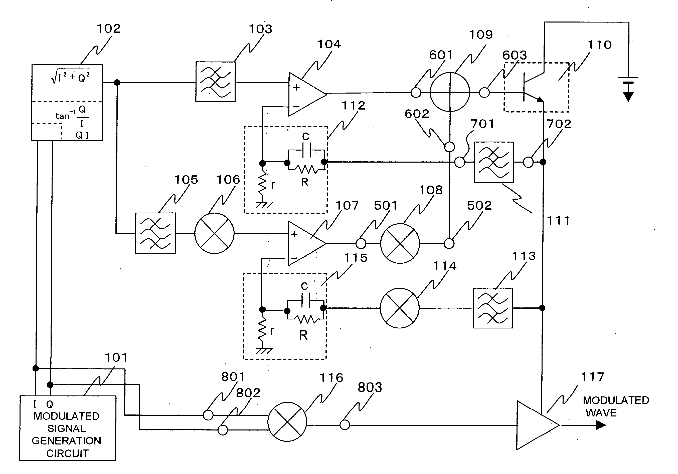
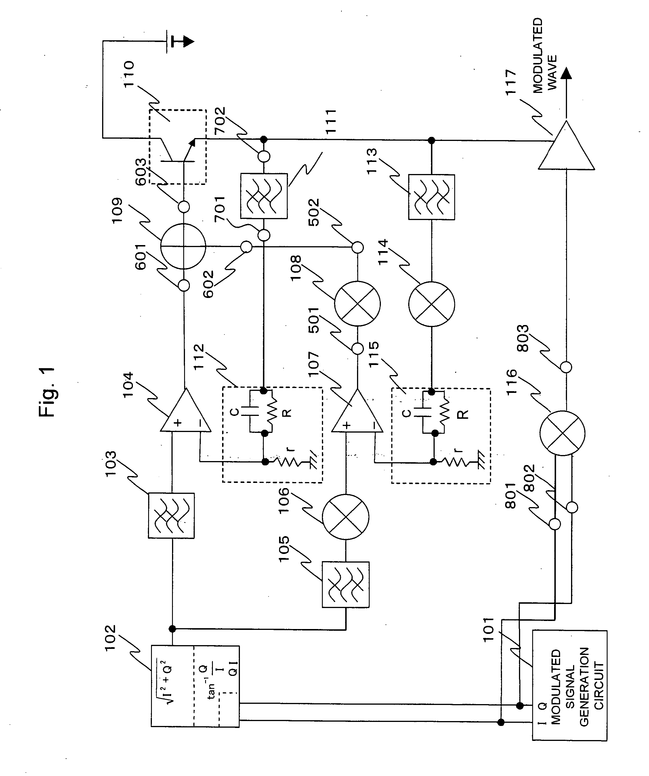
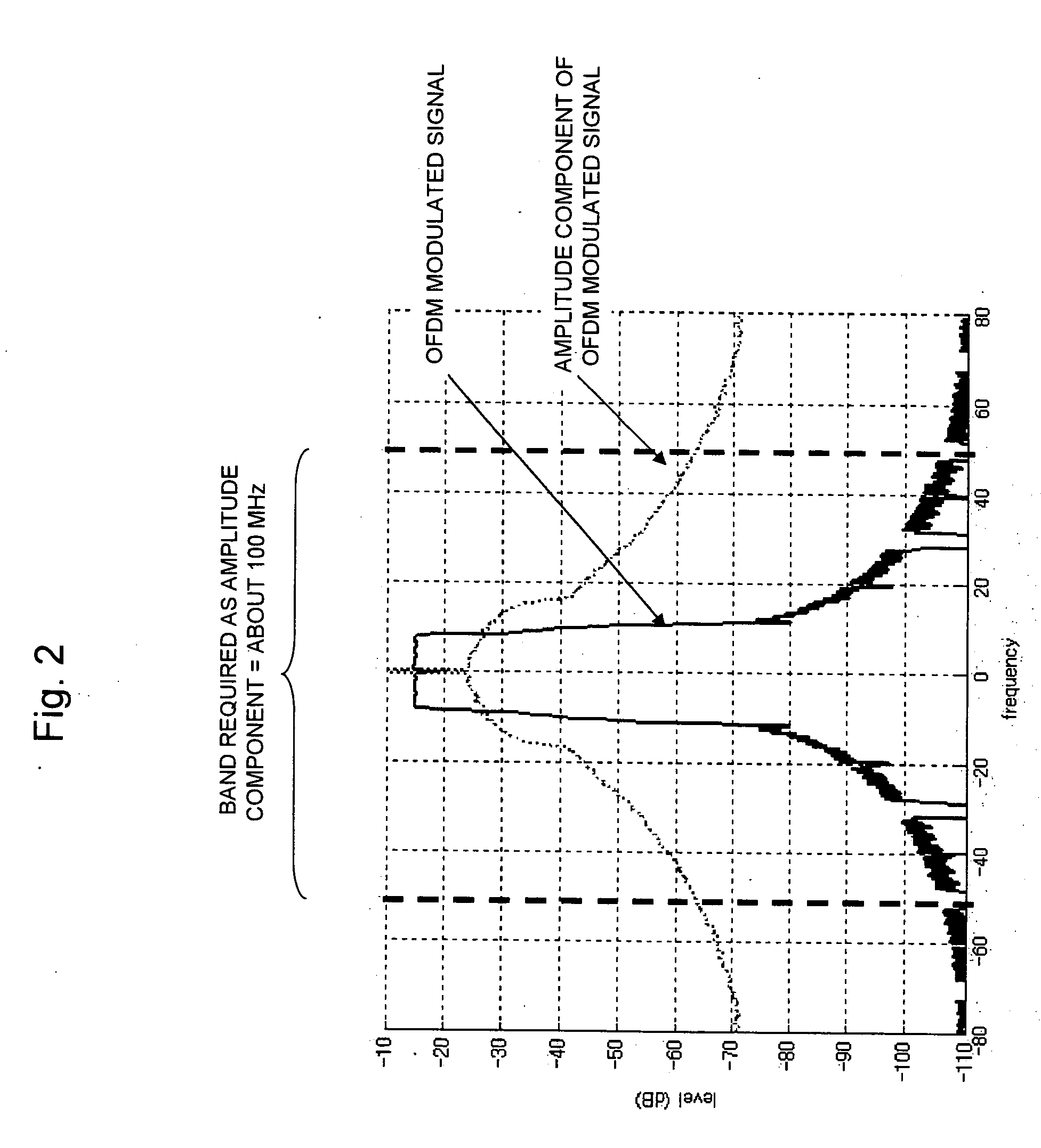
[0084] Hereinafter, the first embodiment according to first and second inventions will be described by reference to the drawings. In this embodiment, an OFDM modulation method is employed as a modulation method. The system using the OFDM modulation method includes, for example, a wireless LAN system of the IEEE 802.11a standard. In the wireless LAN system, a primary modulation such as 64 QAM, 16 QAM, QPSK, or BPSK is performed for each of the orthogonal 52 sub-carriers and then Inverse Fast Fourier Transform (IFFT) is performed, and then all the sub-carriers are added up with each other to obtain the OFDM modulating signal. A symbol rate before the IFFT is set to 20 MHz and the IFFT size is a power value of 2 proximate to 52, i.e., 64. As a result, a data rate provided to the respective sub-carriers after serial parallel conversion is 20 MHz / 64, i.e., 312.5 kHz. Hence, the lowest frequency of the sub-carriers is 312.5 kHz, while the higher-order sub-carrier has the frequency, which ...
second embodiment
[0136] The second embodiment of the present invention will be described by reference to FIG. 10.
[0137] This embodiment is different from the first embodiment that the phase component detected by the detection circuit 102 is input as the modulating signal into the frequency conversion circuit 116.
[0138] Other configurations, as well as their effects and operations, are same as those of the first embodiment, so that the description thereof will be omitted here. The effects obtained by the configuration of this embodiment are as follows. In the first embodiment, when the first frequency conversion means 116 and the high-frequency power amplifier 117 are internally configured by multistage circuits, the back off operation is required for a block or an amplifier stage not involving the saturation operation. The back off operation decreases the efficiency of such block or amplifier stage. However, since the complete constant envelope signal is input in this embodiment, the back off oper...
third embodiment
[0139] The third embodiment of the present invention will be described by reference to FIG. 11.
[0140]FIG. 11 shows a configuration of the third embodiment.
[0141]FIG. 11 shows the configuration which, in the case that the configuration of the first embodiment is implemented using a plurality of integrated circuits, should be included in the respective integrated circuits. The transmitter circuit is configured by three integrated circuits 1101, 1102, and 1103.
[0142] The integrated circuit 1101 integrates the modulating signal generating circuit 101, the detection circuit 102, the frequency selecting circuit 103 and 105, and the frequency conversion circuit 106.
[0143] The integrated circuit 1102 integrates the operational amplifiers 104 and 107, the adder 109, the frequency selecting circuits 111 and 113, the frequency conversion circuits 116, 114 and 108, and the feedback circuits 112 and 115.
[0144] The integrated circuit 1103 integrates the high-frequency power amplifier 117 and...
PUM
 Abstract
Description
Claims
Application Information
 - R&D
- Intellectual Property
- Life Sciences
- Materials
- Tech Scout
- Unparalleled Data Quality
- Higher Quality Content
- 60% Fewer Hallucinations
Browse by: Latest US Patents, China's latest patents, Technical Efficacy Thesaurus, Application Domain, Technology Topic, Popular Technical Reports.
© 2025 PatSnap. All rights reserved.Legal|Privacy policy|Modern Slavery Act Transparency Statement|Sitemap|About US| Contact US: help@patsnap.com


