
Rewritable optical information recording medium, recording and reproducing methods, as well as recording and reproducing apparatus

a technology of optical information and recording medium, which is applied in the direction of optical recording/reproducing/erasing methods, instruments, and thermal imaging, etc., can solve the problems of difficult to manufacture inexpensive optical recording medium, difficult to achieve long-time recording stability, and toxic alloys, etc., to achieve low viscosity, less power, and more power

Inactive Publication Date: 2006-04-27
SONY CORP +1
View PDF8 Cites 55 Cited by
  • Summary
  • Abstract
  • Description
  • Claims
  • Application Information

AI Technical Summary

Benefits of technology

[0023] Further, erasure of recorded information, that is, the recorded mark can be made by a method of heating the recorded portion and then gradually cooling it. The recorded portion or both the recorded and unrecorded portions may be heated by laser light irradiation. Accordingly, the erasure can be completed only by continuously scanning a track on which information is recorded, with laser light having more power than the laser light used on reproduction and less power than the laser light used on recording. In the case of an optical disc in which a medium rotates at a high speed, erasure can be executed by irradiating a track on which the recorded mark has been made or a part of the track with continuous laser light at least once. If the erasing light is applied continuously, the rate at which the recorded mark is cooled becomes lower than the above-mentioned critical cooling rate, which is referred to as slow cooling, a part in the vicinity of the laser spot of the recording film, whose temperature has risen, becomes low in viscosity, making mass transfer easily possible; and the deformed part is planarized, eliminating a trace of the hollow part of the recorded mark, and is hardened again once it returns to its pre-recording shape.

Problems solved by technology

As regards the CD-RW and the DVD-RW, the phase change optical recording medium is made of a chalcogen-containing material such as Te—Ge—Sb alloy or Ag—In—Sb—Te alloy; however, these alloys are toxic.
Since a vacuum deposition method such as a sputtering method or the like is required to form these thin films, and the film structure of a recording medium is complicated and the thickness of each thin film must be controlled precisely, it is difficult to manufacture an inexpensive optical recording medium.
A magneto optical recording medium is conventionally made of an alloy thin film consisting of a rare-earth element such as Gd or Tb and a transition metal such as Fe, Ni, Co, or the like; however, those alloy thin films are easily oxidized by oxygen in moisture and in the air, etc. and therefore must be prevented from being exposed to the air by a protective film such as SiO2 or Si3N4, which shows the difficulty with respect to the long-time recording stability.
Also, since an external magnetic field is required for recording in theory, and further, the optical Kerr effect is used for the reproduction principle of recorded information, there is a disadvantage with a complicated situation in which a polarizing optical system must be used.
On the other hand, a CD-R and DVD-R are optical recording media in which recording films are made of organic dye materials; however, they are write-once type media capable of writing only once and not rewritable.
In addition, since photochromic reaction is used in both recording and reproduction, light resistance with respect to reproducing light is low, and there are problems in stability and repeatability.
Also, being of photon mode, those are highly sensitive and fast in speed but lacking in heat stability as well as in light resistance.
In such cases, if the mixture ratio of light-absorbing dye dispersed in a system is low, the recording sensitivity diminishes because the amount of energy which is absorbed and converted to heat is small, and it becomes difficult to get a large modulation degree because the proportion of dye is low.
On the other hand, if the mixture ratio is high, agglutination, segregation, crystallization and association of dye occur unevenly, causing a signal noise.
Also, unless an appropriate high molecular compound or polymer is selected, there is a disadvantage in which the state of dispersion easily changes with time passed in preservation, even if there is a uniform dispersion at the time of deposition.
Further, regarding the process of making a disc, since it is necessary to select a high molecular compound of a low moisture-absorption nature so as to gain stability in long-time preservation, the downside is that selecting a solvent which dissolves this high molecular compound and also does not attack a substrate often involves difficulties of causing the insufficient repeatability.
Also, in Japanese patent No. 3054770, a method of causing change in the crystallized state, involving reversible change in the oriented direction of molecules, with respect to a recording layer made of organic thin film-like crystals containing optical anisotropy such as fatty acid, a fatty acid derivative, a benzoic acid derivative, or n-alkane to detect differences in polarization characteristics is described; however, the crystallinity degree of those organic thin film-like crystals is uneven, so that the signal noise level tends to increase.
Also, there is a problem in which a polarizing optical system is required for a recording and reproducing apparatus similarly to the case of a magneto optical disc.

Method used


Image

  • Rewritable optical information recording medium, recording and reproducing methods, as well as recording and reproducing apparatus
  • Rewritable optical information recording medium, recording and reproducing methods, as well as recording and reproducing apparatus
  • Rewritable optical information recording medium, recording and reproducing methods, as well as recording and reproducing apparatus

Examples


embodiment 1

[0344] This embodiment is an example of a DVD using blue laser of wavelength λ=405 nm.

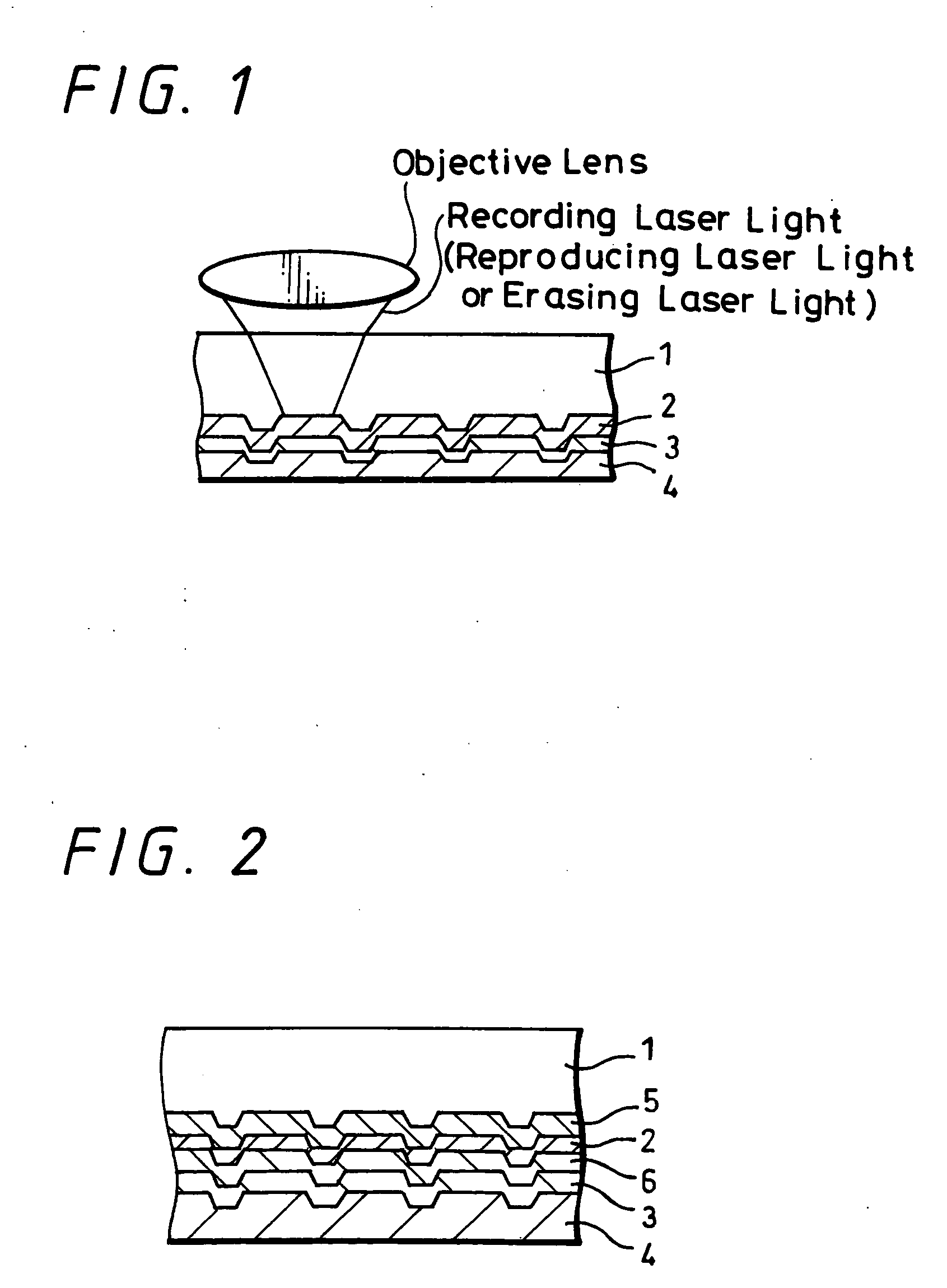
[0345] A polycarbonate substrate the dimensions of which are 0.6 mm in thickness and 120 mm in outer diameter has been made from a stamper with grooves in the shape of 0.6 μm in pitch, 50 nm in groove depth and 0.28 μm in groove width by an injection molding method. The film structure of this example is the same as that shown in FIG. 1. Tetraazaporphyrin dye shown as recording layer 2 by General Formula (A) has been deposited by a vacuum evaporation method on grooves on the substrate so that the film thicness becomes 60 nm. The refractive index and the absorption coefficient of the recording layer 2 were n=1.8 and k=0.05 at 405 nm, respectively. Subsequently, an optical recording medium of the same outer shape as the DVD has been made by depositing a silver reflective layer 3 of 100 nm in thickness on this recording layer by a sputtering method, then depositing UV curing resin [SD17] (produced by...

embodiment 2

[0348] This embodiment is also an example of a DVD using blue laser of wavelength λ=405 nm.

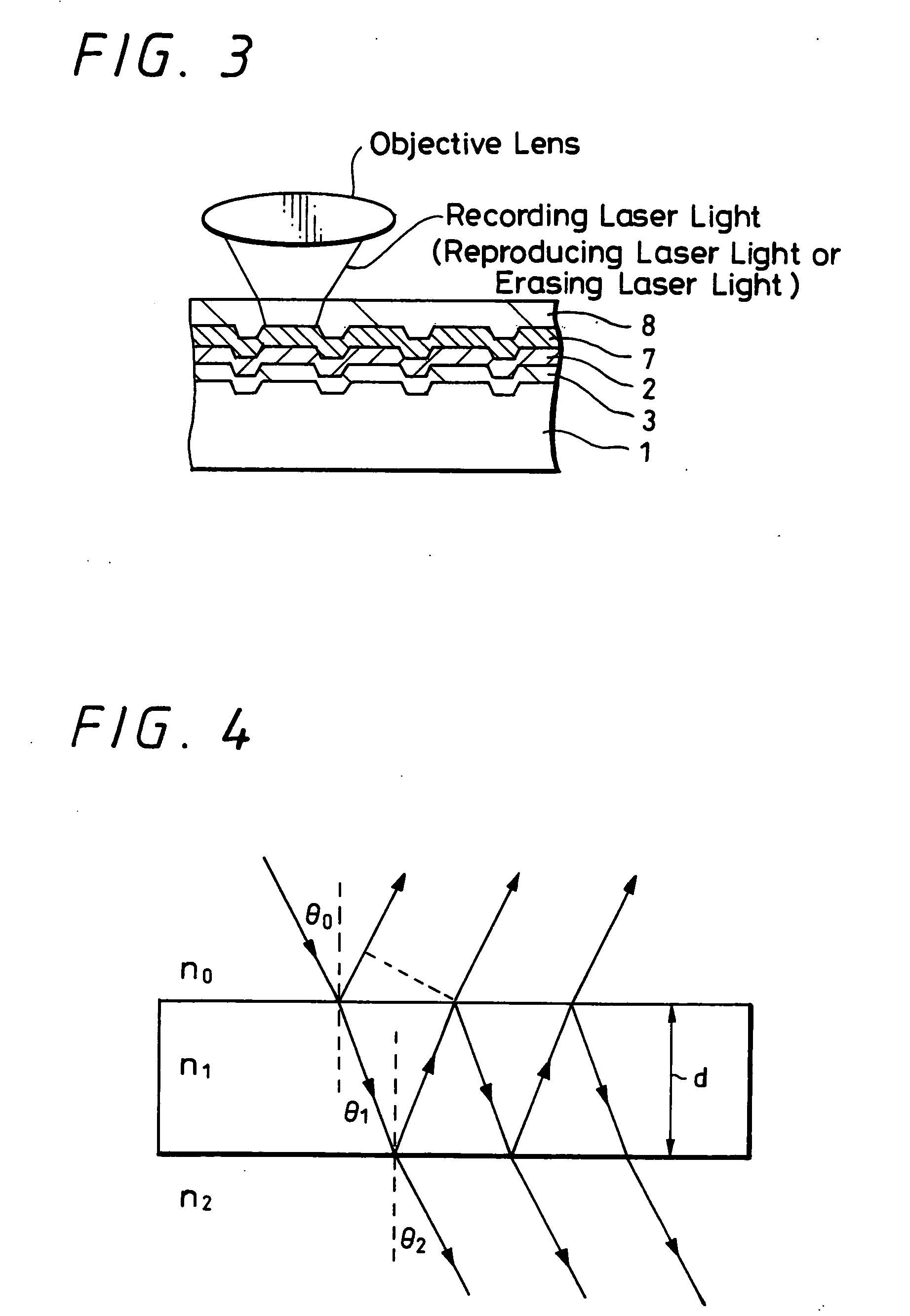
[0349] The same substrate, organic dye recording film, silver reflective film and protective film were used. The film structure of this example is shown in FIG. 2. The difference between this example and Embodiment 1 is that SiO2 of 30 nm in film thickness is deposited by a sputtering method between the substrate 1 and the recording film 3 and between the recording film 3 and the reflective film 5 as a transparent protective layer 5 and as a transparent protective layer 6, respectively. The initial reflectance of the disc was 12%, which virtually corresponds to the calculated value.

[0350] A simple repetitive signal corresponding to the pit length of 0.5 μm was recorded on the same condition as Embodiment 1.

[0351] When the recorded portion was reproduced at a reproducing power of 0.5 mW, the C / N ratio=59 dB was confirmed. FIG. 9 shows the RF signal output concerning this recording pattern.

[...

embodiment 3

[0353] This embodiment is an example of a DVR (an optical disc in which recording and reproduction are performed through a light-transmissive layer of 10 to 177 μm in thickness) using blue laser of wavelength λ=405 nm.

[0354] An example of a film structure in FIG. 3 concerning a recording medium capable of favorably recording and reproducing in an optical system of wavelength 405 nm and NA=0.85 is shown. Here note that guide grooves with a track pitch of 0.64 μm are formed in a polycarbonate substrate 1 and the width of the guide grooves is set to 50% so that recording can be done both on lands and grooves. Specifically, the track pitch is virtually 0.32 μm. Also, the depth of each groove is 40 nm. A silver alloy reflective film 2 of 12 nm in thickness was deposited thereon by a sputtering method, and diazaporphyrin dye shown by General Formula (B) written below is used to form an organic dye film 3 by a vacuum evaporation method.

[0355] The organic dye film was 75 nm in thickness...


PUM


Abstract

A rewritable optical information recording medium including a recording layer composed of an organic dye film is provided, in which recording and erasing information can be performed reversibly by laser light irradiation. A rewritable optical information recording medium including at least one organic dye film which is substantially made of only at least one kind of organic dye compounds as a recording film is provided. The recording and erasure of information are performed by a reversible physical change of the organic dye film substance caused by laser light irradiation. Specifically, data recording is performed by a physical change locally caused by the irradiation of recording laser light, data reproduction is performed by detecting change in intensity of returned light of reproducing laser light having less power than the recording laser light, and data erasure is performed by applying at least once continuous light or pulse light having laser power more than the reproducing laser light and less than the recording laser light. The physical change is a change in shape.

Description

TECHNICAL FIELD [0001] The present invention relates to a novel rewritable optical information recording medium including a recording layer made of an organic dye film, in which recording and erasing of information can be reversibly performed by irradiating laser light, and further, to a recording and reproducing method as well as a recording and reproducing apparatus in which the medium is used. BACKGROUND ART [0002] Lately, as optical recording media widely used on the market, there are write-once organic optical discs (so-called CD-R, DVD-R and the like), rewritable phase change optical discs (so-called CD-RW, DVD-RW and the like), and further, magneto optical discs and the like. [0003] As regards the CD-RW and the DVD-RW, the phase change optical recording medium is made of a chalcogen-containing material such as Te—Ge—Sb alloy or Ag—In—Sb—Te alloy; however, these alloys are toxic. Moreover, a dielectric film made of a sulfide, an oxide, or a nitride such as ZnS, ZnS—SiO2, SiO2,...

Claims


Application Information

Patent Timeline
IPC IPC(8): G11B7/24C07D487/22G11B7/0045G11B7/244G11B7/248G11B7/249
CPCG11B7/00452G11B7/249G11B7/248G11B7/244B41M5/26
Inventor TAMADA, SAKUYAIWAMURA, TAKASHISABI, YUICHIOYAMADA, MITSUAKIYAMAMOTO, MASANOBUKOIKE, TADASHIMISAWA, TATSUMIOGISO, AKIRANARA, RYOUSUKETOKUHIRO, JUNTSUKAHARA, HISASHI
Owner SONY CORP
Learn More