Ceramic member and manufacturing method for the same
a technology of ceramic components and manufacturing methods, applied in the field of ceramic components, can solve the problems of poor mechanical strength of yttria such as bending strength or fracture toughness, and the new problems described below, and achieve the effects of high mechanical strength, high mechanical strength, and high mechanical strength
- Summary
- Abstract
- Description
- Claims
- Application Information
AI Technical Summary
Benefits of technology
Problems solved by technology
Method used
Image
Examples
working example 1
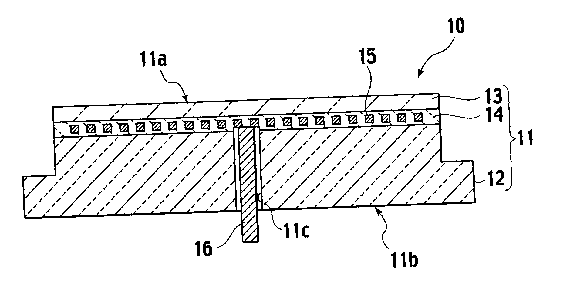
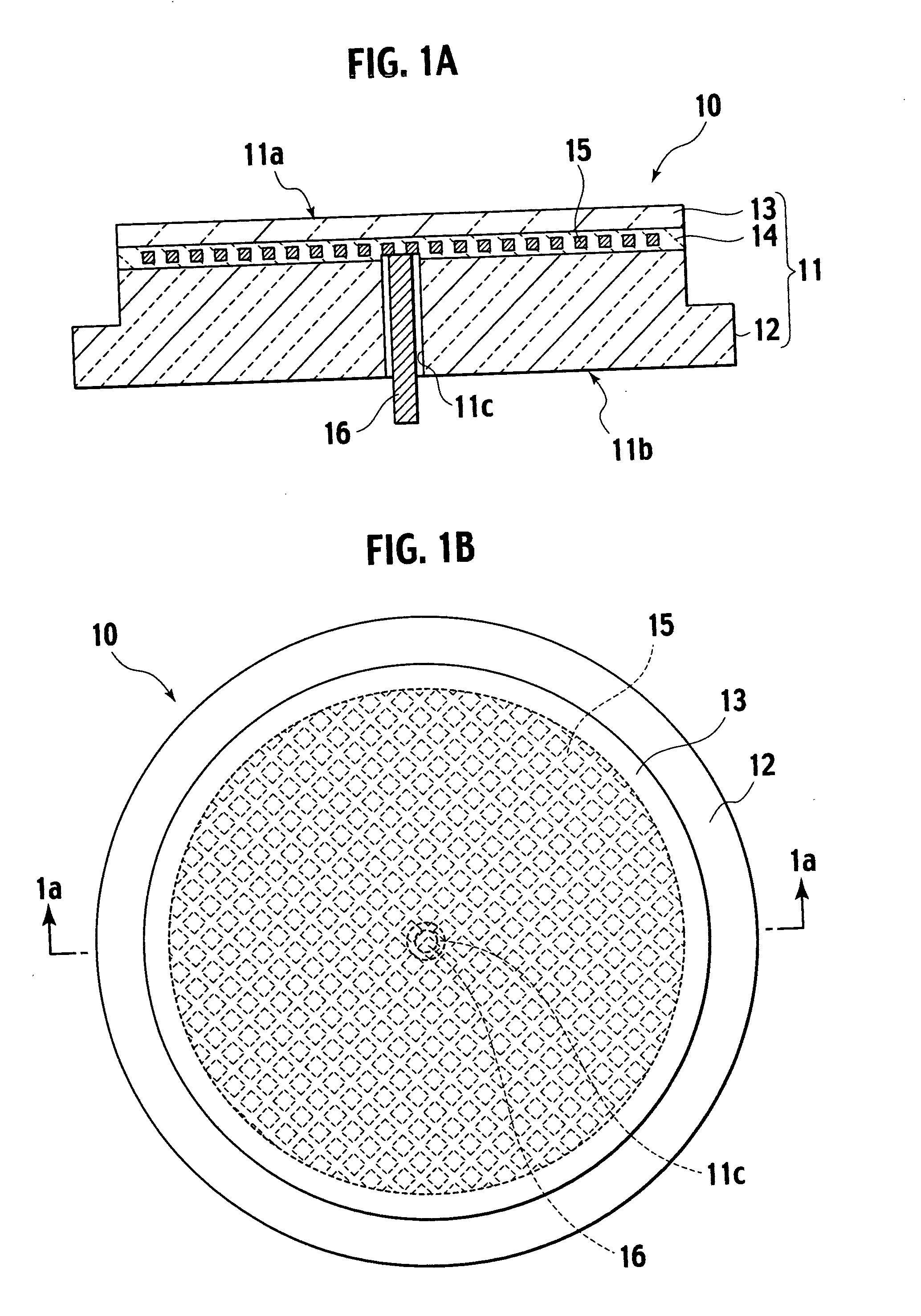
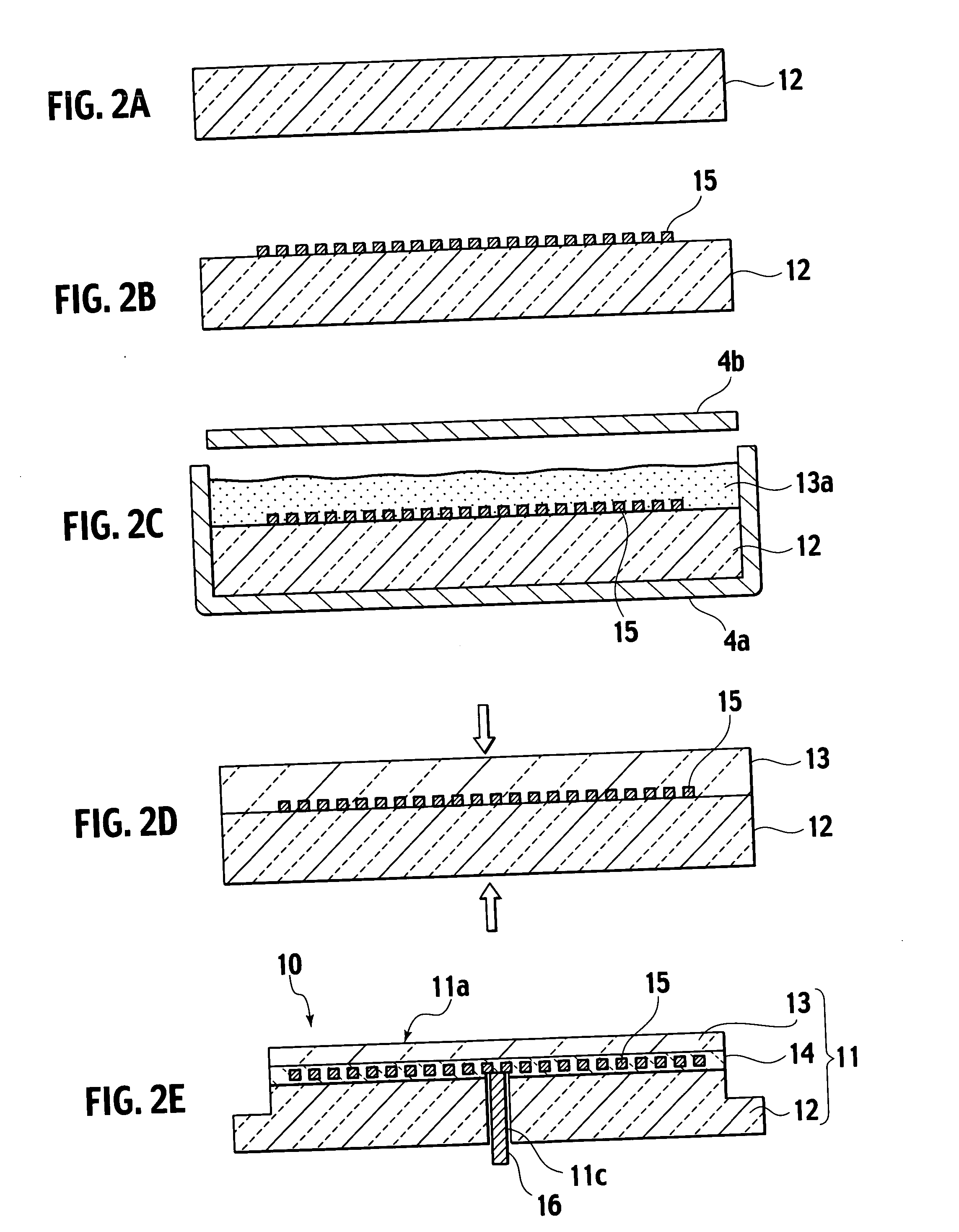
[0122] An yttria powder having a purity of 99.9 weight % and an average particle size of 1 μm is prepared as a raw powder for an yttria sintered body. Water, a dispersant, and polyvinyl alcohol (PVA) as a binder are added to the yttria powder and then mixed for 16 hours using a trommel, resulting in slurry. The resulting slurry is sifted through a 20 μm sieve, removing impurities, and then subjected to spray drying using a spray drier, resulting in yttria granules having an average particle diameter of approximately 80 μm. The resulting granules are calcined in a furnace, which is atmospheric pressure and oxidized atmosphere at a temperature of 500° C. According to this calcining, degreasing and adjusting of the water content to be about 1% or less are conducted.
[0123] The yttria granules are filled in a metal mold. A pressure of 10 kg / cm2 is then applied thereupon by a uniaxial pressing apparatus, resulting in an yttria compact. At this time, the density of the yttria compact is a...
working example 2
[0128] As with the working example 1, yttria granules and alumina granules are prepared. First, the yttria granules are filled in a metal mold. An yttria compact is then formed while applying a pressure of 10 kg / cm2 using a uniaxial pressing apparatus. At this time, the density of the resulting yttria compact is adjusted to be 1.8 g / cc. A niobium electrostatic electrode mesh (mesh electrode) having a wire diameter of 0.12 mm is mounted on the yttria compact. The alumina granules are filled on the yttria compact and the electrostatic electrode and then subjected to press forming, resulting in a layered body including the yttria compact, the electrostatic electrode, and the alumina compact. Note that the yttria compact is formed while applying a pressure of 10 kg / cm2 so that the density of the yttria compact after formation of the layered body can be adjusted to 2 g / cc or less.
[0129] The resulting layered body is put in a carbon mold, and sintered by hot pressing. Specifically, sinte...
working example 3
[0130] An alumina powder having a purity of 99.9 weight % and an average particle size of 0.5 μm, and an yttria stabilized zirconia powder (8 mol % YSZ) having a purity of 99.9 weight % and an average particle size of 0.1 μm are prepared as a raw powder for an alumina sintered body. Water, a dispersant, and polyvinyl alcohol (PVA) as a binder are added to 95 weight % alumina and 5 weight % yttria stabilized zirconia powder, and then mixed using a trommel for 16 hours, resulting in slurry. The resulting slurry is then sifted through a 20 μm sieve, removing impurities, and then subjected to spray drying using a spray drier, resulting in alumina / zirconia granules having an average particle diameter of approximately 80 μm.
[0131] Next, the alumina / zirconia granules are filled in a metal mold. Forming an alumina compact including zirconia is then conducted while applying a pressure of 50 kg / cm2 using a uniaxial pressing apparatus. The resulting alumina compact is filled in a carbon mold ...
PUM
| Property | Measurement | Unit |
|---|---|---|
| Temperature | aaaaa | aaaaa |
| Fraction | aaaaa | aaaaa |
| Thickness | aaaaa | aaaaa |
Abstract
Description
Claims
Application Information
 - R&D
- Intellectual Property
- Life Sciences
- Materials
- Tech Scout
- Unparalleled Data Quality
- Higher Quality Content
- 60% Fewer Hallucinations
Browse by: Latest US Patents, China's latest patents, Technical Efficacy Thesaurus, Application Domain, Technology Topic, Popular Technical Reports.
© 2025 PatSnap. All rights reserved.Legal|Privacy policy|Modern Slavery Act Transparency Statement|Sitemap|About US| Contact US: help@patsnap.com


