Suppression method of radionuclide deposition on reactor component of nuclear power plant and ferrite film formation apparatus

a technology of ferrite film and radionuclide, which is applied in the direction of nuclear engineering, nuclear elements, greenhouse gas reduction, etc., to achieve the effect of suppressing radionuclide deposition

Inactive Publication Date: 2006-03-30
HITACHI-GE NUCLEAR ENERGY LTD
View PDF14 Cites 19 Cited by
  • Summary
  • Abstract
  • Description
  • Claims
  • Application Information

AI Technical Summary

Benefits of technology

[0014] First, when an oxide film is formed in a high temperature atmosphere such as a reactor water temperature range (for example 250˜300 ° C.) during service operation, the diffusion velocity of oxygen generated by radiolysis of water into metal parent material of a component that the oxide film is to be formed, and oxidation velocity of parent material is fast, so that the oxide film (inner layer) formed initially becomes much in chromium component contained in stainless steel.
[0020] If it is possible to form only a magnetite film such as the outer oxide film A2, B2 under the temperature condition (for example, 100° C. or lower) that the diffusion rate of dissolved oxygen into metal parent material is slow, it is considered to be able to suppress taking in of cobalt of radionuclides.
[0023] According to the above, the ferrite films formed on the surfaces of members composing a nuclear power plant are ferrite films that magnetite is a main component, corresponding to the sample E in FIG. 4, because the temperature at time of forming the films is lower than the temperature in the core service operation. That is, in the case where the temperature at time of ferrite film formation is in a temperature range at time of service operation of the core, since a diffusion velocity of an oxidizing agent (oxidizer) is fast, a conventional inner oxide film that chromium is a main component is formed, and cobalt is taken in there. On the contrary, in the case where the temperature at time of formation of the ferrite film is 60° C. to 100° C. which is low, since the diffusion velocity of the oxidizer is slow, the conventional inner oxide film that chromium is a main component is not formed, but a magnetite film that taking in of radionuclides is less and iron is a main component, corresponding to the sample E in FIG. 4 is formed, whereby it is possible to suppress deposition of radionuclides onto components.
[0026] Therefore, the radionuclide deposition suppression method according to the present invention is preferable to be practiced after termination of a decontamination process such as chemical decontamination and so on conducted commonly in the nuclear power plant. Concretely, it is preferable to practice the method after a termination stage of the decontamination process and before starting the core. That is, the decontamination such as chemical decontamination or the like is a treatment for removing radionuclides deposited on the surfaces of nuclear power plant components in contact with reactor water together with oxide films. Therefore, the radionuclide deposition suppression method according to the present invention is practiced under the condition that surfaces of parent material of components to be treated are exposed by the decontamination, and any natural oxide film does almost not exist. As a result, a magnetite film which is a kind of ferrite film according to the present invention is formed directly on the surface of component, so that it is possible to effectively suppress deposition of radionuclides. Thereby, it is possible to reduce exposure dose at time of regular inspection working.
[0030] According to the present invention, it is possible to effectively suppress deposition of radionuclides on components of a nuclear power plant.

Problems solved by technology

However, even if the above-mentioned measures for corrosion prevention are taken, very slight metal impurities exist inevitably in the reactor water, so that a part of the metal impurities deposits on the surface of a fuel rod as metal oxide.
As a result, radiations are radiated from the surface of the components, which becomes a cause of radiation exposure on person engaged with regular inspection during the inspection.

Method used


Image

  • Suppression method of radionuclide deposition on reactor component of nuclear power plant and ferrite film formation apparatus
  • Suppression method of radionuclide deposition on reactor component of nuclear power plant and ferrite film formation apparatus
  • Suppression method of radionuclide deposition on reactor component of nuclear power plant and ferrite film formation apparatus

Examples


first embodiment

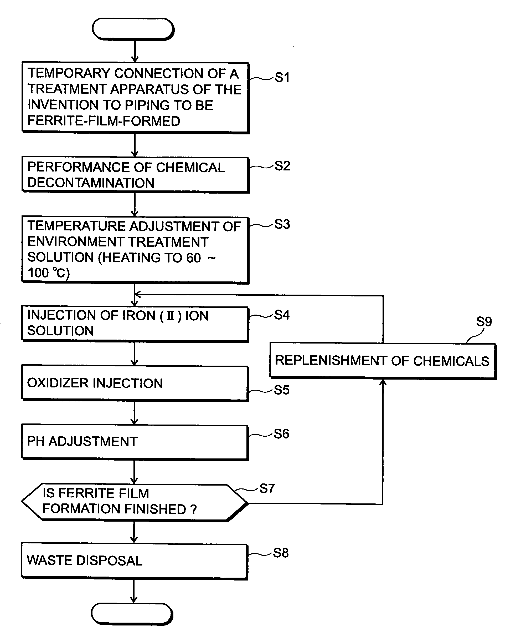
[0050]FIG. 1 shows a flowchart of an embodiment of a radionuclide deposition suppression method of the present invention, FIG. 5 shows a schematic diagram of a whole system construction of an embodiment in which the present invention is applied to recirculation piping of a nuclear power plant, and FIG. 6 shows a schematic diagram of a detailed system construction of a film forming apparatus for practicing the radionuclide deposition suppression method according to the present invention.

[0051] As shown in FIG. 5, the nuclear power plant comprises a nuclear reactor 1 having fuel rods contained in a pressure vessel, main steam piping 2 connected to the top of the nuclear reactor 1, a steam turbine generator 3 connected to the main steam piping 2, and a condenser 4 connected to a steam outlet of the steam turbine generator 3. The condensate condensed in the condenser 4 is taken out by a condensate pump 5, and returned as feed water for the nuclear reactor 1 through a feed water piping ...

second embodiment

[0068]FIG. 8 shows a system of a concrete embodiment of a portion forming iron (II) ions stored in the chemical tank 49 shown in FIG. 6. In FIG. 8, formic acid solution is stored in a chemical tank 70, and nitrogen from nitrogen bubbling equipment 71 is bubbled in the chemical tank 70, whereby dissolved oxygen is removed. The formic acid from which the dissolved oxygen is removed is transferred to a metal iron dissolution tank 73 by an injection pump 72. Metal iron 74 is set in the metal iron dissolution tank 73, and iron (II) ion is dissolved by the formic acid transferred thereto. At this time, nitrogen from the nitrogen bubbling equipment 71 is bubbled in the metal iron dissolution tank 73. The formic acid solution in the metal iron dissolution tank 73 does not substantially include dissolved oxygen, so that the iron (II) ion is almost not oxidized to iron (III) ion. The formic acid solution which dissolved the iron (II) ion is transferred to the chemical tank 49 by an injection ...

third embodiment

[0070]FIG. 9 shows a system of another embodiment of iron (II) ion formation shown in FIG. 8. In the present embodiment, carbonic water instead of formic acid in the embodiment of FIG. 8 is used as an iron ion solution. Carbonic acid is stored in a chemical tank 76, carbon dioxide supplied form a carbon dioxide bubbling equipment 77 is bubbled into the chemical tank 76, and saturated carbonic water of one atmosphere is formed. The formed one atmosphere saturated carbonic water is transferred to the metal iron dissolution tank 73 by the injection pump 72. Iron (II) carbonate 78 is contained in the metal iron dissolution tank 73, and the one atmosphere saturated carbonic water is dissolved. Further, carbon dioxide from the carbon dioxide bubbling equipment 71 is bubbled into the metal ion dissolution tank 73. By the way, according to the literature (Chemical Unabridged Dictionary 5, page 729 (1997), Reduced-size edition), usually, the solubility of iron (II) carbonate is 0.065 g / 100 g...


PUM


Abstract

A method of suppressing deposition of radionuclides on components of a nuclear power plant comprises forming a ferrite film by contacting a first chemical including iron (II) ions, a second chemical for oxidizing the iron (II) ions to iron (III) ions, and a third chemical for adjusting the pH of a processing solution containing a mixture of the first and second chemicals to be 5.5 to 9.0 with the metal member surface in a time period from a finishing stage in decontamination step of removing contaminants formed on the surface of metal member composing the nuclear power plant, and suppressing deposition of radionuclides on the metal member by the ferrite film.

Description

BACKGROUND OF THE INVENTION [0001] 1. Field of the Invention [0002] The present invention relates to a method of suppressing deposition of radionuclides on components of a power plant such as a nuclear power plant, and a ferrite film formation apparatus for performing the radionuclide deposition suppression method. [0003] 2. Background Arts [0004] For example, in a nuclear power plant of boiling water type reactor (hereunder abbreviated as BWR), the heat generated by fuel is effectively transferred to cooling water by forcibly circulating the cooling water by a primary loop recirculation pump and internal pumps inside the nuclear reactor comprising a reactor pressure vessel and control rods contained therein. Most of the steam generated from the cooling water in this way is used for driving a steam turbine generator, the steam exhausted from the steam turbine is condensed in a condenser, and the condensate condensed in the condenser is almost fully deaerated and supplied again as co...

Claims


Application Information

Patent Timeline
IPC IPC(8): G21C19/42
CPCG21C17/0225G21C19/42G21F9/28G21F9/12G21F9/06Y02E30/30
Inventor HOSOKAWA, HIDEYUKINAGASE, MAKOTOISHIDA, KAZUSHIGEWADA, YOICHIUSUI, NAOSHIAIZAWA, MOTOHIROFUSE, MOTOMASA
Owner HITACHI-GE NUCLEAR ENERGY LTD
Why Eureka
Try Eureka