
Bond coat for a thermal barrier coating system and related method thereof

a thermal barrier coating and bonding technology, applied in the direction of superimposed coating process, vacuum evaporation coating, coatings, etc., can solve the problems of unsatisfactory rocket engine application and overheating of the bond coating, and achieve efficient bonding, limited oxidation or non-oxidation conditions, and high temperature capability

Inactive Publication Date: 2006-03-23
UNIV OF VIRGINIA ALUMNI PATENTS FOUND
View PDF4 Cites 31 Cited by
  • Summary
  • Abstract
  • Description
  • Claims
  • Application Information

AI Technical Summary

Benefits of technology

[0010] The present invention provides a method and an apparatus for efficiently applying a bond coat and related coating systems to a surface that can survive the thermal gradient that is encountered in very high temperature, high heat flux environments such as a rocket engine. To overcome the limitations incurred by conventional TBC system deposition methods, exemplary embodiments use an electron or other energetic, beam directed vapor deposition (DVD) technique to evaporate and deposit the related coating systems. The present invention comprises a TBC system for rocket engine combustors or similar applications with very high temperature capability in limited oxidation or non-oxidation conditions. High temperature bond coat materials are provided, such as Fe, Ni, Cr, Pt, Ir, Ti, Zr, Ta, Nb, and W.
[0012] In one modality, the present invention DVD technique uses the combination of an energetic beam source (e.g., electron or high intensity laser, beam gun) (capable of evaporating material in a low vacuum environment) and a combined inert gas / reactive gas carrier jet of controlled composition to create engineering films. In this system, the vaporized material can be entrained in the carrier gas jet and deposited onto the substrate at a high rate and with high materials utilization efficiency. The velocity and flux of the gas atoms entering the chamber, the nozzle parameters, and the operating chamber pressure can all be significantly varied, facilitating wide processing condition variation and allowing for improved control over the properties of the deposited layer. In particular, under some (higher pressure / high evaporation rate) processing conditions, nanoscopic particles can be reactively formed in the vapor and incorporated in the coating.
[0014] In a third modality, dispersoids are created before deposition and are entrained in the noble gas stream and used to transport the bond coat vapor to the component surface. In modalities one, two, and three a plasma may also be used to control the bond coat structure. In all modalities, the result is a low cost deposition approach for applying bond coats which can have compositions and dispersoids distributions which are difficult to deposit using other conventional approaches.

Problems solved by technology

An important problem, for example, that must be addressed is overheating of the bond coat in case of a local spall of the TBC layer.
However, in a rocket engine, the need for oxidation resistance and formation of a TGO may not always be critical since reducing conditions sometimes prevail for most or all of the duty cycle.
The conventional MCrAlY and PtAl bond coats on nickel alloys melt at or below about 1,300 C and are unsatisfactory for rocket engine applications.

Method used


Image

  • Bond coat for a thermal barrier coating system and related method thereof
  • Bond coat for a thermal barrier coating system and related method thereof
  • Bond coat for a thermal barrier coating system and related method thereof

Examples


Embodiment Construction

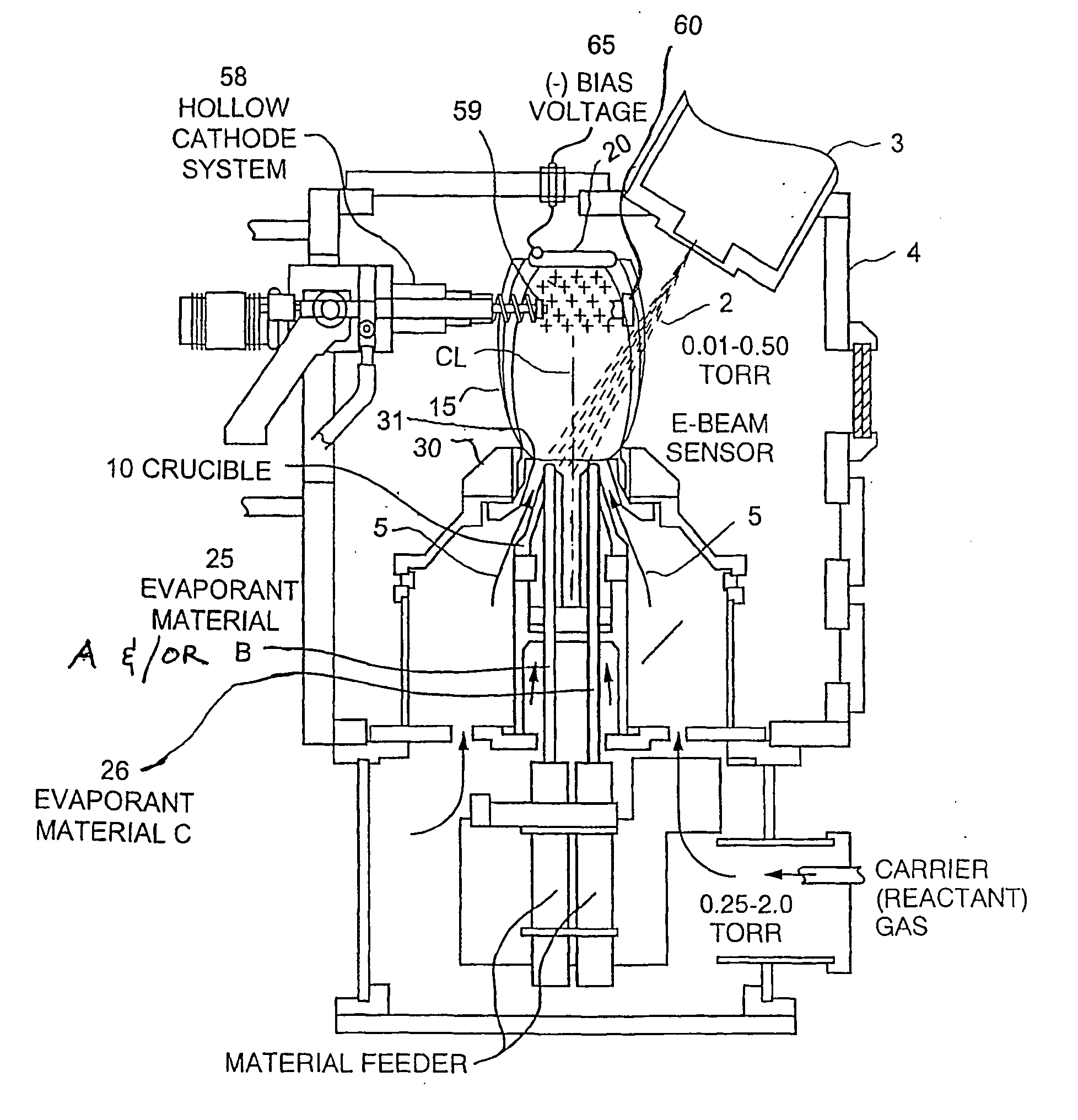
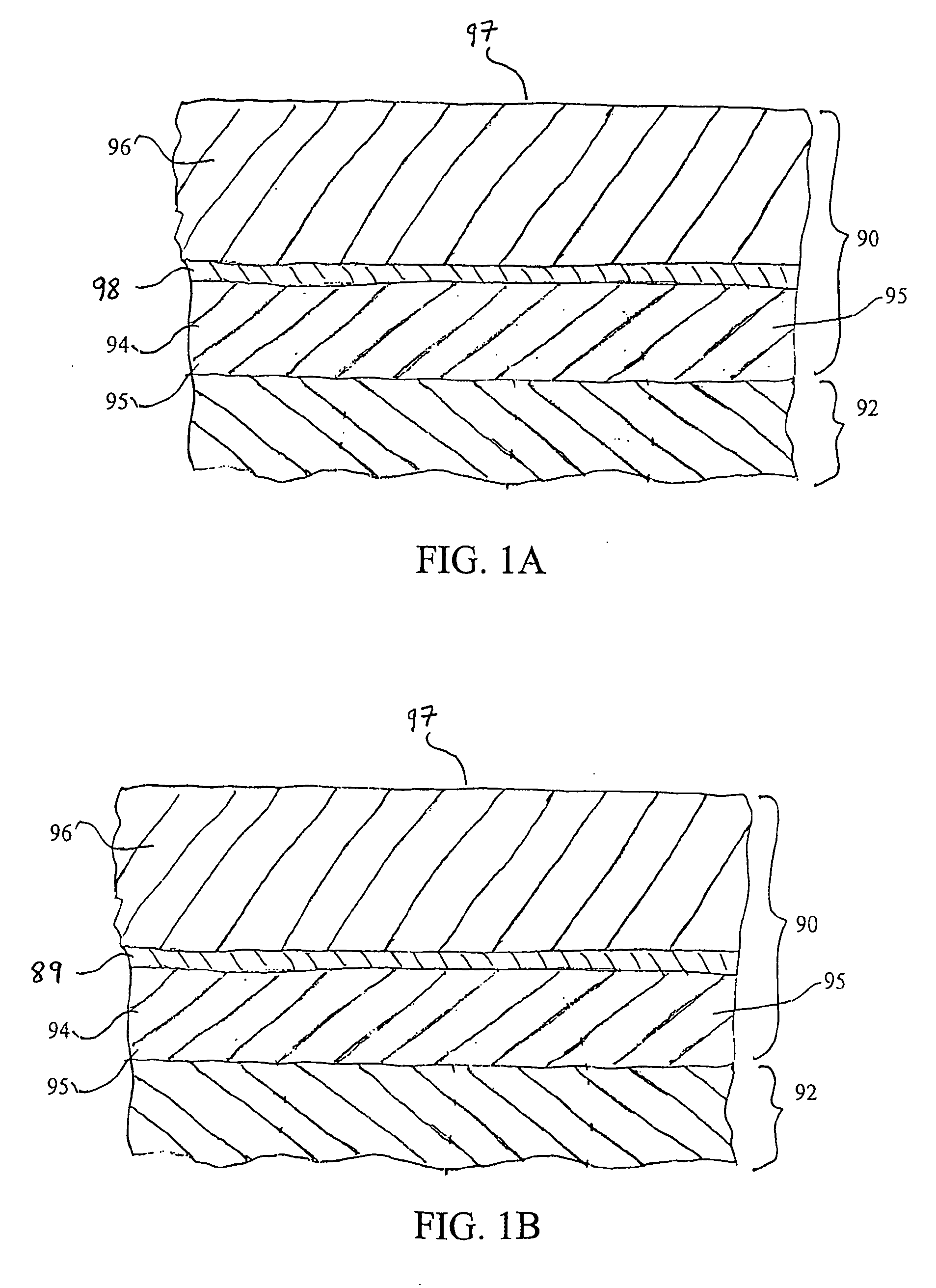
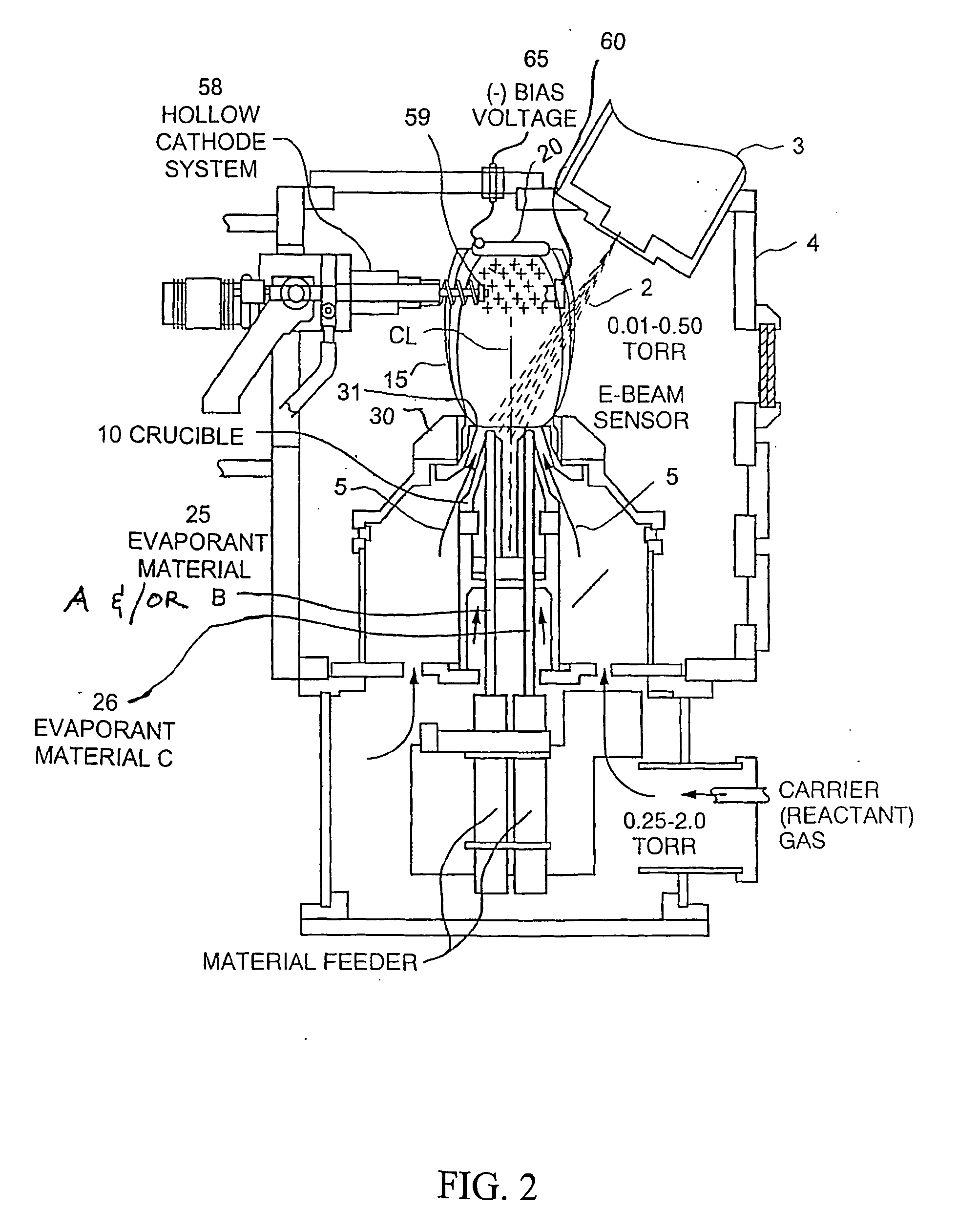
[0043] The present invention provides, among other things, TBC systems comprising a higher temperature capable bond coat system that is not necessarily based on formation of an alumina thermally grown oxide (TGO). While conventional bond coat compositions that form alumina TGO have lower melting points than required, for the present invention oxidation protection is not necessarily required under reducing conditions. An embodiment of the present invention TBC system is specifically designed for rocket engine and other related applications, however it may be applicable to any application that sees high temperatures and either non-oxidizing or limited oxidizing conditions. Materials for the bond coat layer may include; but not limited thereto iron (Fe), nickel (Ni), Chronium (Cr), Plantinum (Pt), Iridium (Ir), titanium (Ti), zirconium (Zr), niobium (Nb), tantalum (Ta), and tungsten (W) and their alloys. Functionally layering and or grading of these materials is also provided in variou...


PUM

PropertyMeasurementUnit
Pressureaaaaaaaaaa
Temperatureaaaaaaaaaa
Distanceaaaaaaaaaa

Abstract

Method and Apparatus for efficiently applying a bond coat and related coating systems to a surface that can survive the thermal gradient that is encountered in very high temperature, high heat flux environments such as a rocket engine. An apparatus for efficiently applying coating systems using a vapor or cluster deposition technique such as a directed vapor deposition (DVD) approach, and more particularly providing a thermal barrier coating (TBC) system applications with very high temperature utility in cither oxidizing or non-oxidizing conditions.

Description

CROSS-REFERENCE TO RELATED APPLICATIONS [0001] The present invention claims priority from U.S. Provisional Application Ser. No. 60 / 428,523 filed Nov. 21, 2002, entitled “Thermal Barrier Coating Systems for Rocket Engine Applications and Related Method thereof,” the entire disclosure of which is hereby incorporated by reference herein. [0002] The present application is also related to International Application No. PCT / US03 / 36035, filed Nov. 12, 2003, Attorney Docket No. 00837-02, entitled “Extremely Strain Tolerant Thermal Protection Coating and Related Method and Apparatus Thereof,” of which is assigned to the present assignee and is hereby incorporated by reference herein in its entirety. [0003] The present application is also related to International Application No. PCT / US03 / 23111, filed Jul. 24, 2003, entitled “Method and Apparatus for Dispersion Strengthened Bond Coats for Thermal Barrier Coatings,” of which is assigned to the present assignee and is hereby incorporated by refer...

Claims


Application Information

Patent Timeline
IPC IPC(8): C23C16/00C23C14/06C23C14/08C23C14/30C23C14/32C23C28/00
CPCC23C14/0635C23C14/0641C23C14/083C23C14/16C23C14/228C23C14/32C23C28/3455C23C28/321C23C28/3215C23C28/322C23C28/34C23C28/341C23C28/345Y02T50/67Y02T50/60
Inventor WORTMAN, DAVIDJWADLEY, HAYDN N.G
Owner UNIV OF VIRGINIA ALUMNI PATENTS FOUND
Learn More