
Magnetic recording medium and magnetic recording method

a recording medium and magnetic technology, applied in the direction of defrosting, instruments, domestic cooling apparatus, etc., can solve the problems of insufficient prevention of magnetic interaction between the recording layer and the backing layer, low magnetic field of the backing layer upon readout, and difficult recording, so as to reduce the amount of magnetic field that is released from the backing layer upon readout, and suppress the generation of striped magnetic domains.

Inactive Publication Date: 2006-03-23
SHOWA DENKO KK
View PDF11 Cites 0 Cited by
  • Summary
  • Abstract
  • Description
  • Claims
  • Application Information

AI Technical Summary

Benefits of technology

[0012] An object of the present invention is to provide a magnetic recording medium which can record information without failure with low magnetic field strength and can produce high signal outputs, suppressing medium noises, and a magnetic recording method for recording in the magnetic recording medium.
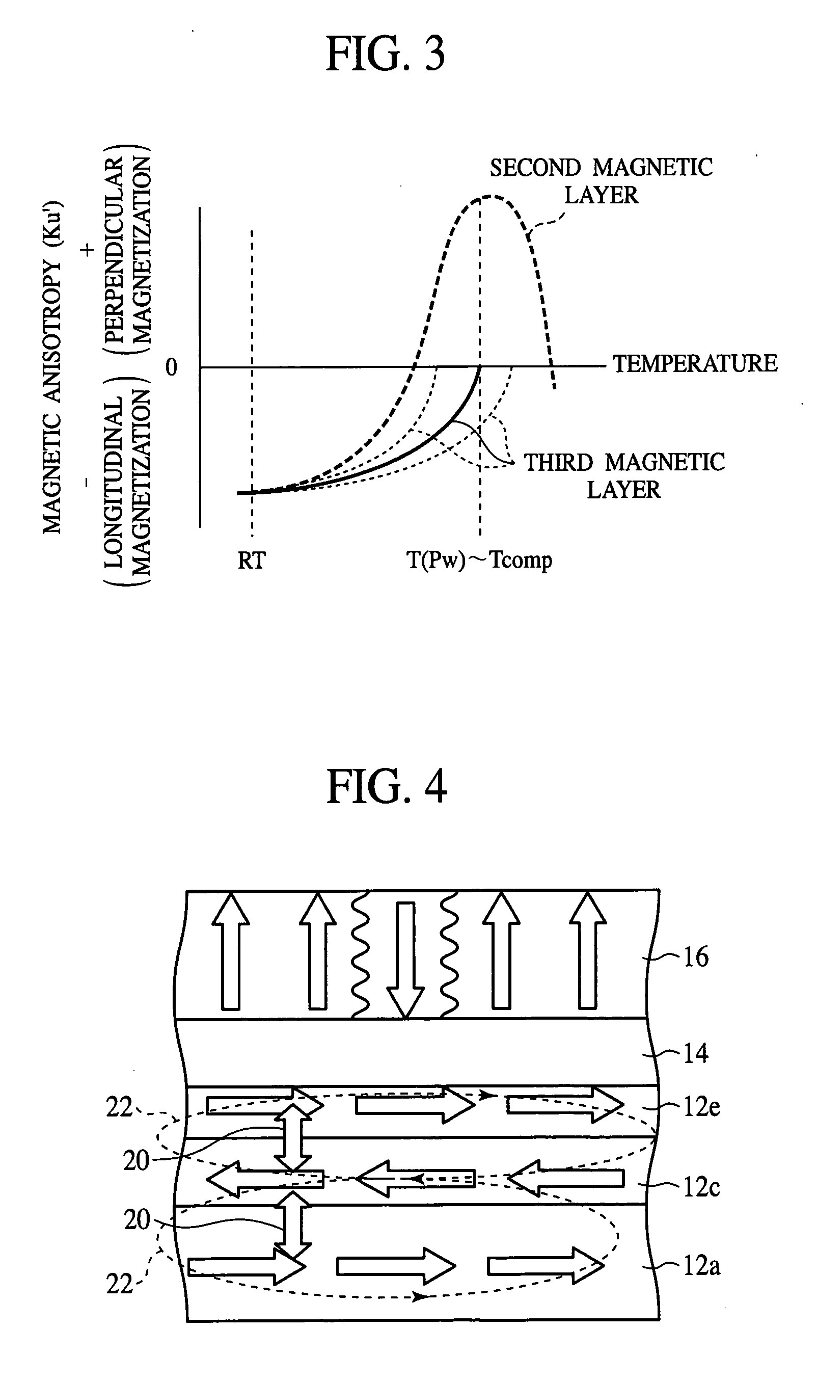
[0016] According to the present invention, the backing layer is formed of the first magnetic layer and the second magnetic layer of a ferromagnetic material magnetized in a direction opposite to the first magnetic layer, whereby antiferromagnetic exchange interconnection is formed between the first magnetic layer and the second magnetic layer, whereby a closed magnetic circuit is formed in the backing layer. Thus, the leakage magnetic field from the backing layer upon readout is decreased, and simultaneously the generation of the striped magnetic domains is suppressed, and the medium noise can be decreased.
[0017] The second magnetic layer become a longitudinal magnetization film at a readout temperature and becomes a perpendicular magnetization film at a recording temperature, whereby the effect of the above-described antiferromagnetic exchange interconnection can be obtained on the readout, and the recording magnetic field can be concentrated on a recording region on the recording, and the recording magnetic field sensitivity can be increased. Thus, the recording magnetic field gradient can be made acute, whereby the transition noise between adjacent magnetic domains can be decreased.
[0018] The second magnetic film becomes a perpendicular magnetization film to thereby act to draw in the recording magnetic field, whereby the recording magnetic field strength or the output of the laser for increasing the temperature can be decreased, and accordingly the electric power consumption can be decreased.
[0019] The third magnetic layer magnetized in a direction opposite to the second magnetic layer is further formed on the second magnetic layer to thereby form antiferromagnetic exchange interconnection between the second magnetic layer and the third magnetic layer, whereby the increase of the leakage magnetic field can be suppressed, and the saturation magnetization strength at the surface of the backing layer (the third magnetic layer) can be increased. Accordingly, the effect of enhancing the signal output due to the image reflection effect can be increased. The effect of decreasing the medium noise can be obtained, which can increase the S / N ratio.
[0020] The third magnetic layer has the Currie temperature near a recording temperature, whereby the magnetic field from the third magnetic layer on the recording can be decreased, and the third magnetic layer is prohibited from influencing the recording magnetic field.

Problems solved by technology

When perpendicular magnetic components are generated in the backing layer, even these components are detected upon the readout, causing medium noises.
However, when the intermediate layer is too thick, the magnetic fluxes from the head cannot arrive at the backing layer, which makes the recording difficult.
On the other hand, when the intermediate layer is too thin, the magnetic interaction between the recording layer and the backing layer cannot be sufficiently prevented, and the resultant fluctuations cause medium noises.
When the backing layer has an inversely magnetized domain, forming a 180° magnetic domain wall, leakage fluxes theretrhough become spike-shaped noise and multiplexed on readout signals, which often increase the medium noises.

Method used


Image

  • Magnetic recording medium and magnetic recording method
  • Magnetic recording medium and magnetic recording method
  • Magnetic recording medium and magnetic recording method

Examples


first embodiment

A FIRST EMBODIMENT

[0029] The magnetic recording medium and the magnetic recording method according to a first embodiment of the present invention will be explained with reference to FIGS. 1 to 6.

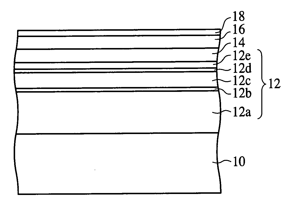
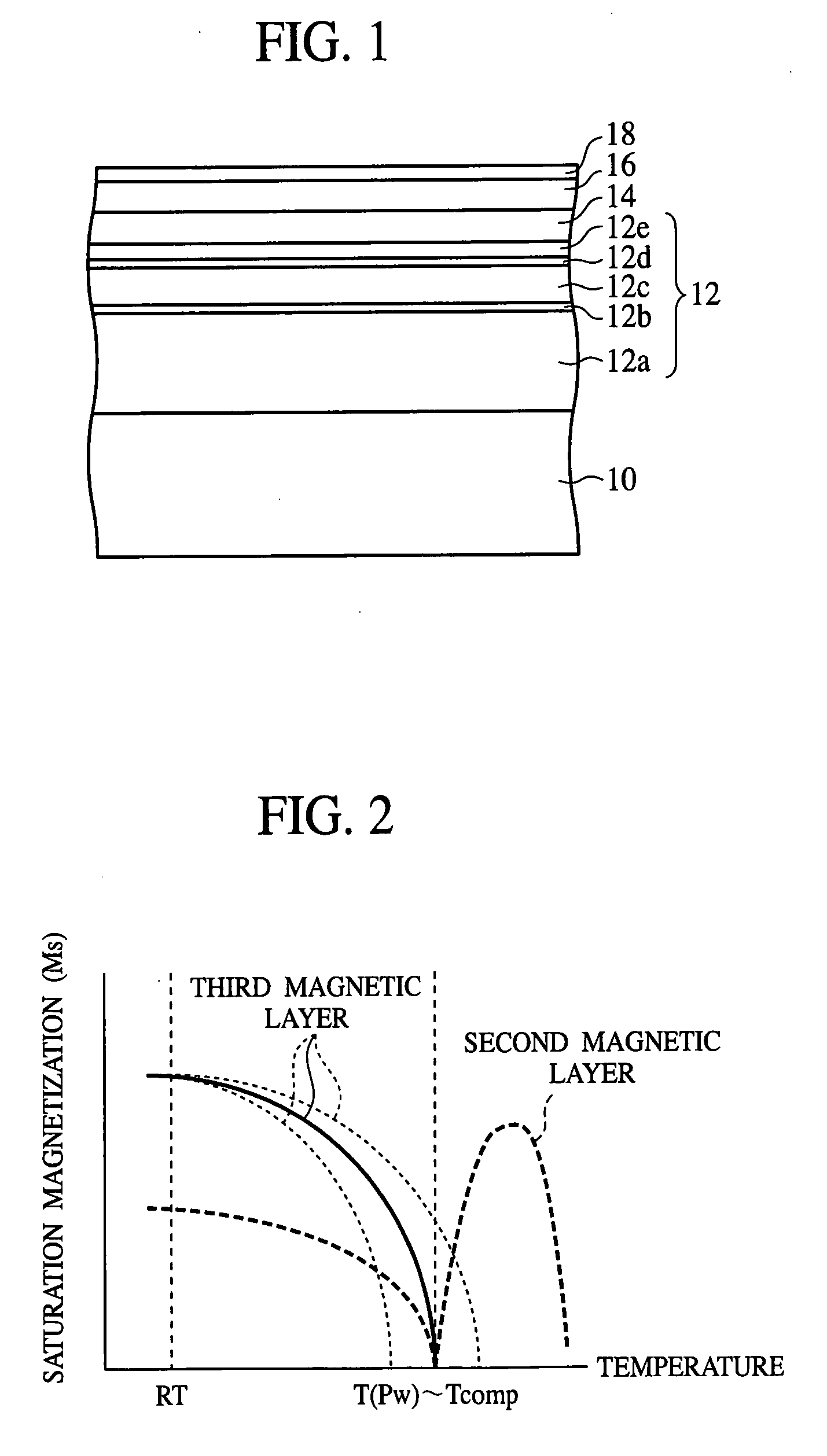
[0030]FIG. 1 is a diagrammatic sectional view of the magnetic recording medium according to the present embodiment, which shows a structure thereof. FIG. 2 is a graph of the temperature characteristics of the saturation magnetization strength of the backing layer of the magnetic recording medium according to the present embodiment. FIG. 3 is a graph of the temperature characteristics of the magnetic anisotropy of the backing layer of the magnetic recording medium according to the present embodiment. FIG. 4 is a view explaining the readout principle of the magnetic recording medium according to the present embodiment. FIG. 5 is a view explaining the recording principle of the magnetic recording medium according to the present embodiment. FIG. 6 is a graph of the overwrite characteristics for...

second embodiment

A SECOND EMBODIMENT

[0074] The magnetic recording device according to a second embodiment of the present invention will be explained with reference to FIG. 7.

[0075]FIG. 7 is a diagrammatic sectional view of the magnetic recording device according to the present embodiment, which shows a structure thereof.

[0076] A magnetic disc 36 is secured to the end of a spindle 30. The magnetic disc 36 is a magnetic recording medium comprising a magnetic layer 34 formed on a glass substrate 32, which is machined in a disc. The magnetic disc 36 can be the magnetic recording medium according to, e.g., the first embodiment of the present invention. The spindle 30 can be rotated by spindle motor (not shown).

[0077] On the side of the magnetic layer 34 of the magnetic disc 36, a GMR (Giant Magneto Resistive Head) 38 using giant magnetoresistance effect is disposed. The GMR head 38 is secured to an arm (not shown). The GMR head 38 can be moved to the arbitrary recording region of the magnetic disc 36 ...


PUM

PropertyMeasurementUnit
recording currentaaaaaaaaaa
ferromagneticaaaaaaaaaa

Abstract

The magnetic recording medium comprises a backing layer 12 including a first magnetic layer 12a, a second magnetic layer 12c which is formed over the first magnetic layer 12a, is ferromagnetic and is magnetized in a direction opposite to the first magnetic layer 12a, and a third magnetic layer 12e formed over the second magnetic layer 12c and magnetized in a direction opposite to the second magnetic layer 12c; and a perpendicular magnetic recording layer 16 for recording magnetic information formed over the backing layer 112. Antiferromagnetic exchange interconnection is formed between the first magnetic layer 12a and the second magnetic layer 12c and between the second magnetic layer 12c and the third magnetic layer 12e.

Description

CROSS-REFERENCE TO RELATED APPLICATIONS [0001] This application is based upon and claims the benefit of priority from the prior Japanese Patent Application No. 2004-248294, filed on Aug. 27, 2004, the entire contents of which are incorporated herein by reference. BACKGROUND OF THE INVENTION [0002] The present invention relates to a magnetic recording medium and a magnetic recording method for recording in the magnetic recording medium, more specifically, a magnetic recording medium to be used in perpendicular magnetic recording and a magnetic recording method for recording in the magnetic recording medium. [0003] Hard disc devices, which are magnetic recording devices, are widely used in computers, and external storage media, such as various kinds of portable information terminals, e.g., mobile personal computers, game devices, digital cameras, car navigation systems, etc. [0004] Recently, perpendicular magnetic recording media, which can be made more coercive force twice or more in...

Claims


Application Information

Patent Timeline
Patent Type & Authority Applications(United States)
IPC IPC(8): G11B5/82
CPCG11B5/66G11B5/82G11B2005/0029G11B2005/0021G11B2005/0002G11B5/678Y10S428/90
Inventor SUGIMOTO, TOSHIOINAMURA, RYOSAKU
Owner SHOWA DENKO KK
Learn More