
Filtering apparatus, back wash method therefor, filtering device and power plant

a filtering device and filtering technology, applied in lighting and heating equipment, sedimentation settling tanks, separation processes, etc., can solve the problems of affecting the operation of the filter, so as to prevent the damage of the filter and reduce the permeability of the filter

Inactive Publication Date: 2006-03-16
KK TOSHIBA
View PDF17 Cites 1 Cited by
  • Summary
  • Abstract
  • Description
  • Claims
  • Application Information

AI Technical Summary

Benefits of technology

[0028] Accordingly, an object of this invention is to provide a filtering apparatus which is chemically stable and a back wash method for a filtering apparatus, for removing suspended solid contained in hot water properly without considering elution from the filter, for satisfying water quality control because the amount of the elution is little, and for preventing damages of the filter and lowering of permeability of the filter because of the heat cycle.
[0029] Another object of this invention is to provide a filtering device which does not need complex system and additional process to make the filter hydrophilic in every back wash operation, for back washing at high temperature and with convenient system structure.
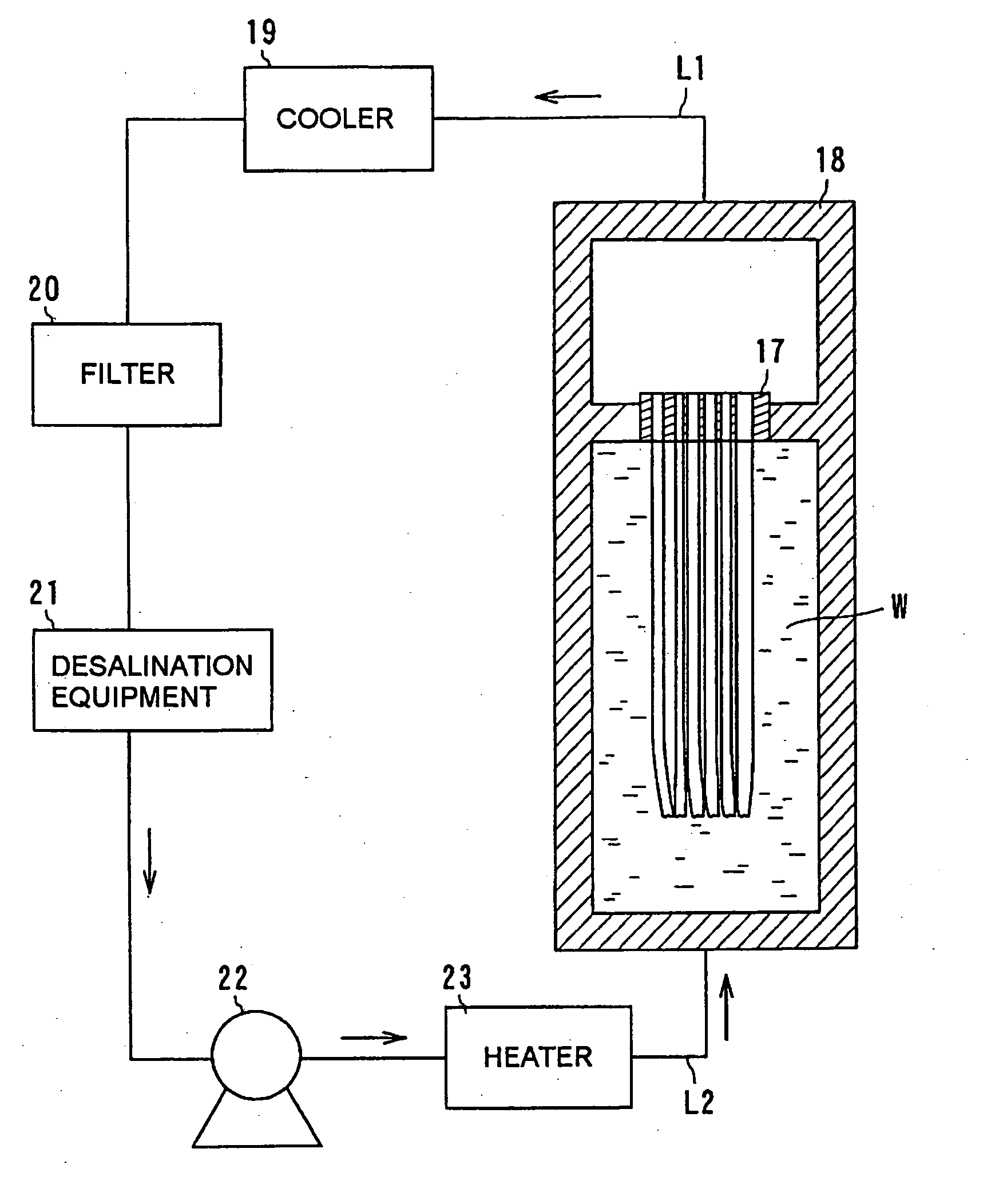
[0035] According to another aspect of this invention, there is provided a filtering device including, a filtering apparatus composed of a vessel with a filtrate accumulation space provided in an upper side thereof and a filter contained in the vessel, a feed inlet line for introducing feed into the filtering apparatus, a filtrate outlet line for letting filtrate flow out of the filtering apparatus, the filter filtering the feed to let filtered feed flow as the filtrate, a back wash tank for storing back wash water to be supplied into the filtering apparatus with a partition which easily passes liquid component and hardly passes gas component to separate the back wash tank into a first compartment and a second compartment, the first compartment being adapted for connecting a gas supply line capable of controlling gas pressure and for supplying the gas to the filtering apparatus, and a make-up water supply line for supplying the back wash water to the filtering apparatus, and the second compartment being connected to the filtrate accumulation space of the filtering apparatus.

Problems solved by technology

However, by using a filtering apparatus with the filter mentioned above, although a filter or a filtration material which has the mechanism to reduce concentration of the suspended solid is installed for suppressing prevention of heat transmission and corrosion inside of piping, since heat-resistant temperature of the above-mentioned hollow fiber filter apparatus made from polyethylene is about 60 degrees Centigrade, it cannot be applied to a feedwater heater.
Moreover, a metal filter has subjects that it is chemically unstable, and a used metallic material may begin to dissolve and corrode or form an oxide film, and thus pores of the filter may be blocked.
However, even if the hollow porosity film itself is a material having sufficient performance from a viewpoint of heat-resistance and elution, the amount of elution from these resins used as an encapsulant is large and inadequate, and it is difficult to apply these resins to a filter for removing suspended solid from hot water in the temperature of over 100 degrees Centigrade, such as feedwater or heater drain of a power plant whose water quality is highly managed.
By installing a filtering apparatus composed of the above-mentioned filter made from polyethylene, suspended solid in condensate at low temperature can be removed, however, the filter made from polyethylene is not applicable for removing suspended solid generated in hot water at a temperature of not less than 100 degrees Centigrade because heat-resistant temperature of the polyethylene filter is low.
Moreover, the metallic filter applied to feedwater at a temperature of over 100 degrees Centigrade tends to be chemically unstable and clogged up with deposit of solid substances, and it may pollute water by elution from the filter material in view of standard water quality control, therefore applying the metallic filter to hot water is difficult.
On the other hand, the electromagnetic filter has low filtering performance because it can remove only magnetized suspended solid, and it is difficult for the electromagnetic filter to reproduce the filter for removing dissociated suspended solid.
Furthermore, the filter shown in FIG. 21 cannot avoid heat cycles for treating hot water of a power plant, and the filter module 104 tends to be damaged due to expansion and contraction and exfoliation of the outer case 101 and the support portion 103, because of differences of their materials and their thermal expansion coefficients.
Moreover, purification process of the system takes additional time and medical fluid processing is also necessary.
Moreover, the back wash process of the filter used at high temperature cannot be carried out at the high temperature, so it needs cooling process before the back wash process and heating process before restarting.
Therefore, it needs to be furnished for cooling and heating, and it additionally takes long time to restart the filter because long cooling time and long heating time is included.
That is, the hollow fiber filter made from polyethylene cannot be applied to a feedwater heater because its heat-resistant temperature is about 60 degrees Centigrade, and the metal filter is chemically unstable and its used metallic material dissolves and its pores may be blocked due to corrosion in proportion to forming an oxide film, and the electromagnetic filter has deferrization performance that is greatly influenced by quality of the suspended solid.
Furthermore, the filter shown in FIG. 21 cannot avoid heat cycles for treating hot water of a power plant, and the hollow porosity film 102 tends to be damaged due to expansion and contraction of the outer case 101 and the support portion 103 whose thermal expansion coefficients differ each other, and thus pollution of water quality is occurred due to the base of the filter.
And it is difficult to reproduce the filter, thus it is difficult to use as a filter for removing suspended solid contained in hot water of a power plant in which highly management of water quality and long-term stable performance are needed.
And excessive purification process of the system and medical fluid processing are also needed.
Moreover, it needs cooling before the back wash process and heating before restarting because it cannot back wash the filter used in high temperature circumstance without cooling, so it needs time and additional facilities for cooling and heating and it takes long time up to restarting.
However, since the fluororesin filter is manufactured by pulling filter base element, if the fluororesin filter contacts with hot water in filtering operation, the fluororesin filter tends to deformed and the permeability of the fluororesin is lowered and damaged because of heat cycle.

Method used


Image

  • Filtering apparatus, back wash method therefor, filtering device and power plant
  • Filtering apparatus, back wash method therefor, filtering device and power plant
  • Filtering apparatus, back wash method therefor, filtering device and power plant

Examples


first embodiment

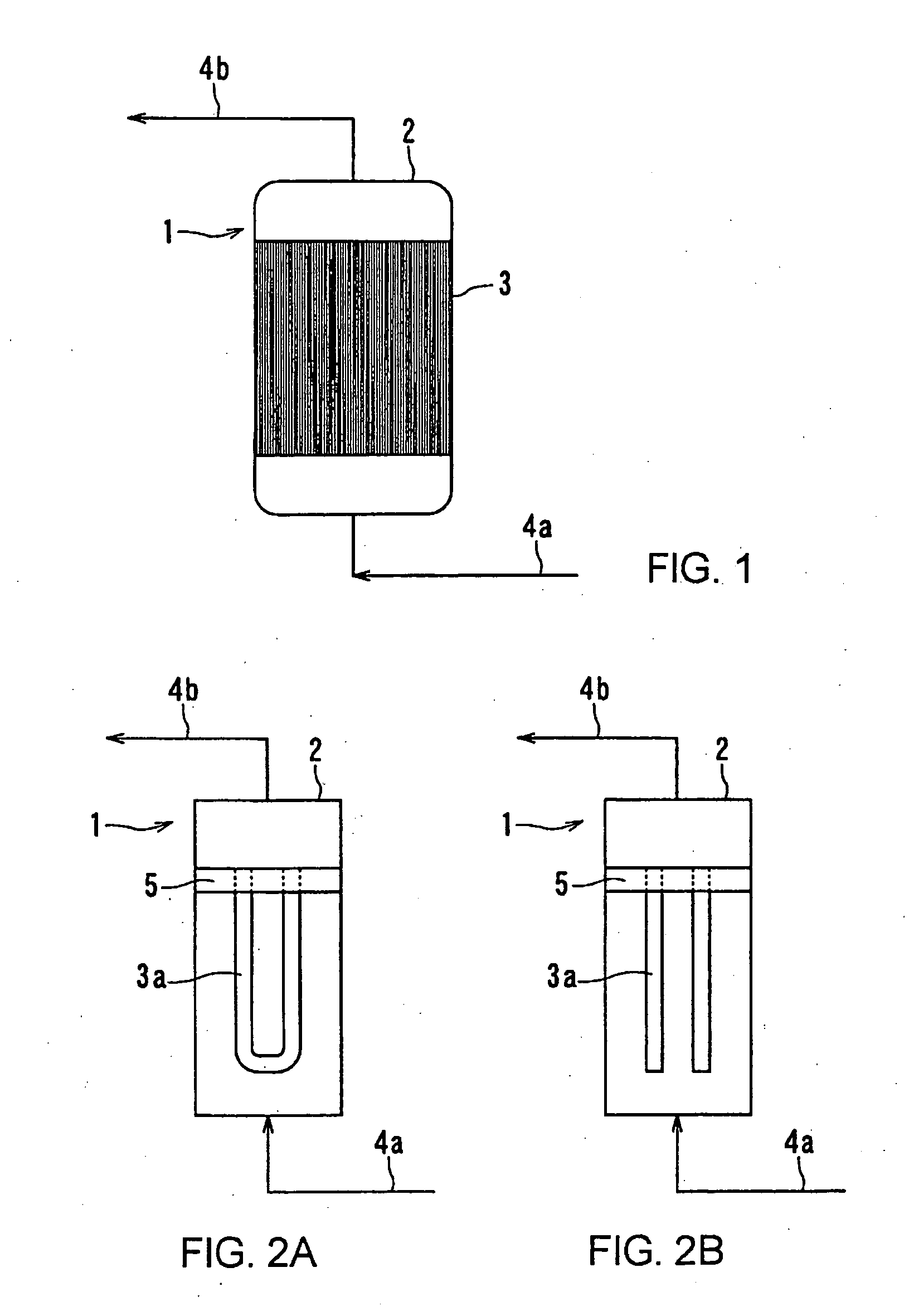
[0061]FIG. 1 is a basic block diagram showing a filtering apparatus of a first embodiment of this invention. As shown in FIG. 1, a filtering apparatus 1 has a tank 2 as a vessel having a filter 3 made of fluororesin inside, and feed inlet line 4a into which feed flows is connected to the bottom of the tank 2, and filtrate outlet line 4b from which filtrate is discharged is connected to the upper part of the tank 2. Here, the feed is a solution before filtering operation by the filter 3, and the filtrate is filtered feed by the filter 3.

[0062] The feed inlet line 4a is, for example, a feedwater line which connects a condenser of a power plant to a reactor pressure vessel or a steam generator (not illustrated), which contains suspended solids, such as iron, during water feeding.

[0063] Moreover, the fluororesin filter 3 made of a polytetrafluoroethylene (PTFE) resin is formed in hollow shape or the shape of pleats, and a plurality of pores whose diameter are in the range between 0.01...

second embodiment

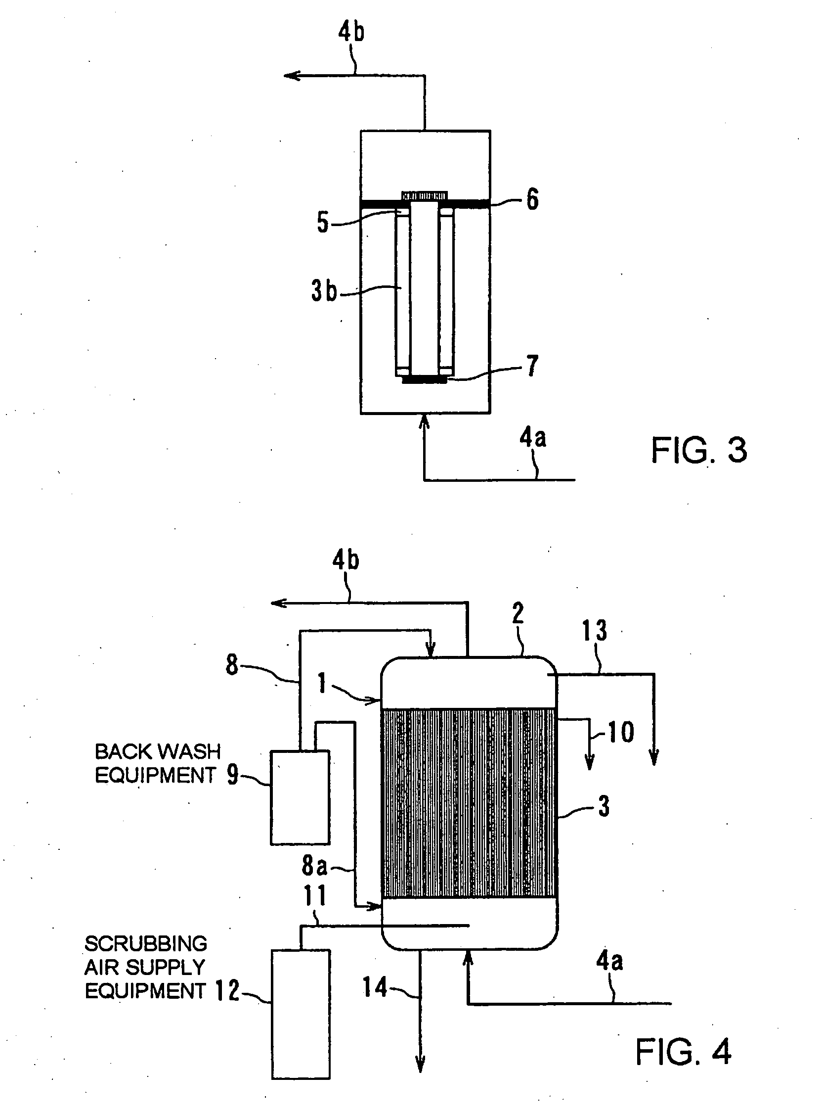
[0076]FIG. 4 is a basic block diagram showing a filtering apparatus of a second embodiment of this invention. In this embodiment, while using the reference number same used in the above-mentioned first embodiment to an identical or corresponding portion of the first embodiment, only different composition and different effect from the above-mentioned first embodiment are explained. And in this embodiment, inside structure of a tank 2 in this embodiment is the same as the above-mentioned first embodiment.

[0077] In this embodiment, in order to remove suspended solid adhering to surface of the fluororesin filter 3, back wash equipment which enables back wash operation by using back wash rinse fluid composed of at least one of water, air, and steam, is installed.

[0078] That is, as shown in FIG. 4, one end of a back wash line 8 for sending back wash rinse fluid into the tank 2 is connected to the upper part of the tank 2, and the other end of the back wash line 8 is connected to a back ...

third embodiment

[0092]FIG. 5 is a basic cross sectional view of a preparing equipment of a filter module of a filtering apparatus of a third embodiment of this invention.

[0093] As shown in FIG. 5, a heater 16 is buried or installed in the vertical direction in a sealed hollow heat treatment vessel 15, and inside of the heat treatment vessel 15 is filled with air A. A filter module 7 made from PTFE, which is a kind of a fluororesin, is contained in the heat treatment vessel 15, and the filter module 7 is heated as the internal air A is heated by the heater 6.

[0094]FIG. 6 is a graph showing relation between the pressure difference and the permeability concerning a filter penetrating hot water without thermal treatment of the filter module and a filter penetrating hot water with heated holding for 1 hour in an atmosphere (air A) at a temperature of 200 degrees Centigrade by using the preparing equipment shown in FIG. 5.

[0095] As shown in FIG. 6, the filter module 17 from which the residual stress i...


PUM

PropertyMeasurementUnit
temperatureaaaaaaaaaa
heat-resistant temperatureaaaaaaaaaa

Abstract

A filtering apparatus having a vessel and a filter made from fluororesin and treated before filtering operation by at least one of adding thermal treatment in gas or liquid and penetrating with fluid composed of hot water or steam at a temperature of less than melting point of the fluororesin.

Description

CROSS-REFERENCE TO RELATED APPLICATIONS [0001] The present application is a continuation of U.S. application Ser. No. 10 / 059,326, filed Jan. 31, 2002, the entire contents of which is incorporated herein by reference.[0002] This application is based upon and claims the benefit of priority from the prior Japanese Patent Applications No. 2001-24855 filed on Jan. 31, 2001, and No. 2001-79375 filed on March 19, 2001, the entire contents of which are incorporated herein by reference. BACKGROUND OF THE INVENTION [0003] 1. Field of the Invention [0004] This invention relates to a filtering apparatus and a filtering device for removing suspended solid contained in hot water and a power plant in which the filtering apparatus or the filtering device is installed. [0005] 2. Description of the Related Art [0006] Conventionally, in a case of removing suspended solid generated from structural material or piping material by a condenser in a power plant, especially removing iron oxide, hollow fiber ...

Claims


Application Information

Patent Timeline
Patent Type & Authority Applications(United States)
IPC IPC(8): B01D29/62B01D29/66B01D61/18B01D63/02B01D63/04B01D63/06B01D65/02B01D65/06B01D67/00B01D71/32B01D71/36C02F1/44F01K21/06F22D11/00F28F19/01
CPCB01D61/18F28F19/01B01D63/023B01D63/024B01D63/043B01D63/061B01D63/067B01D65/02B01D67/0083B01D71/36B01D2321/04B01D2321/08C02F1/444F01K21/06F22D11/006B01D63/021B01D63/0241B01D29/66B01D71/32C02F1/44
Inventor FUJIE, MAKOTONAKAMURA, HIDEKIYAMADA, KAZUYASEKI, SHUJISAKURAI, MANABUFUKUSHIMA, TADASHIIDE, KENICHIRONODA, TETSUYAKOMATSUBARA, MASARU
Owner KK TOSHIBA
Learn More