
Method of conducting a needle biopsy procedure

a biopsy and needle technology, applied in the field of biopsy needles, can solve the problems of needle damage to the tissues, insufficient tissue, and inability to obtain sufficient tissue, so as to reduce the friction between the needle and the surrounding tissue, ease the advance of the needle, and reduce the damage to the tissue

Inactive Publication Date: 2006-03-07
FONAR
View PDF33 Cites 106 Cited by
  • Summary
  • Abstract
  • Description
  • Claims
  • Application Information

AI Technical Summary

Benefits of technology

[0006]The problems encountered in the prior art are overcome in the devices, systems and methods of the present invention by reciprocating the biopsy needle along its longitudinal axis. Such reciprocation or vibration eases the advance of the needle through tissue to the site of interest, decreasing damage to the tissue. It is believed that the rapid movement of the needle decreases the friction between the needle and the surrounding tissue. The reciprocation of the needle also eases the penetration of the site of interest and the collection of tissue at the site of interest, with minimal displacement of the tissue, as the inertia of the tissue of the site of interest maintains the tissue essentially stationary as the tissue is penetrated by the rapidly moving needle. The present invention provides for greater tissue collection than that typically obtained by fine needle aspiration, without the risk of tissue damage and tissue displacement associated with the use of large bore needles. While fine needles are preferably used with the present invention, large bore needles may be used, as well.

Problems solved by technology

However, rather than cutting the tissue to enable collection in the needle bore, the thin needle tends to displace the tissue, especially rigid malignant tissue.
Even after repeated attempts, a sufficient amount of tissue might not be obtained.
However, the risk of damage to the tissues that the needle has to traverse to reach the area of pathology, as well as the risks of bleeding, infection and patient discomfort, rise with increasing needle thickness.
Large needle core biopsy needles may also cause significant damage to certain organs, such as the lungs and the spleen.
As with fine needles, displacement of movable tissues, such as breast tissue, is also a problem.

Method used


Image

  • Method of conducting a needle biopsy procedure
  • Method of conducting a needle biopsy procedure
  • Method of conducting a needle biopsy procedure

Examples


Embodiment Construction

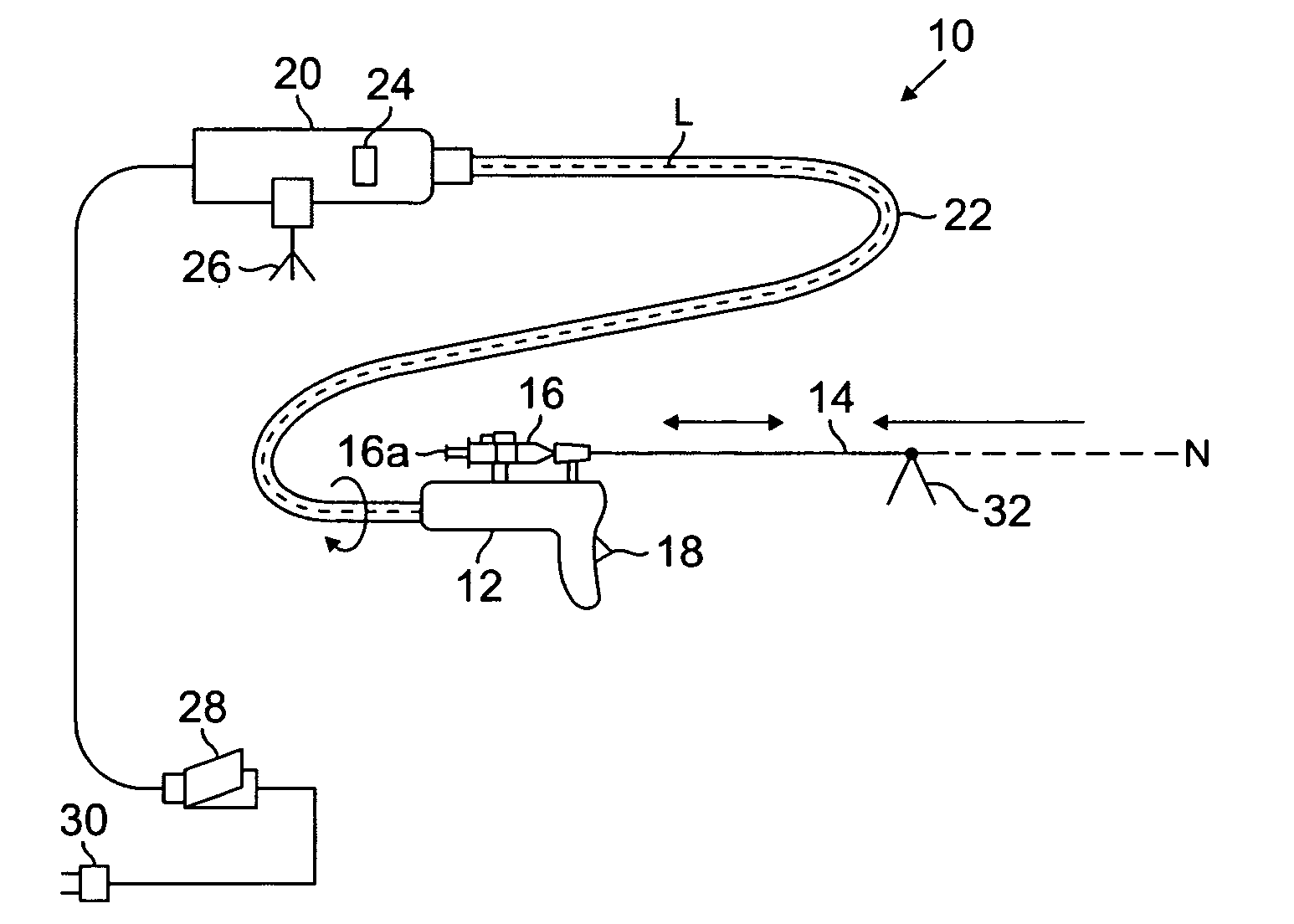
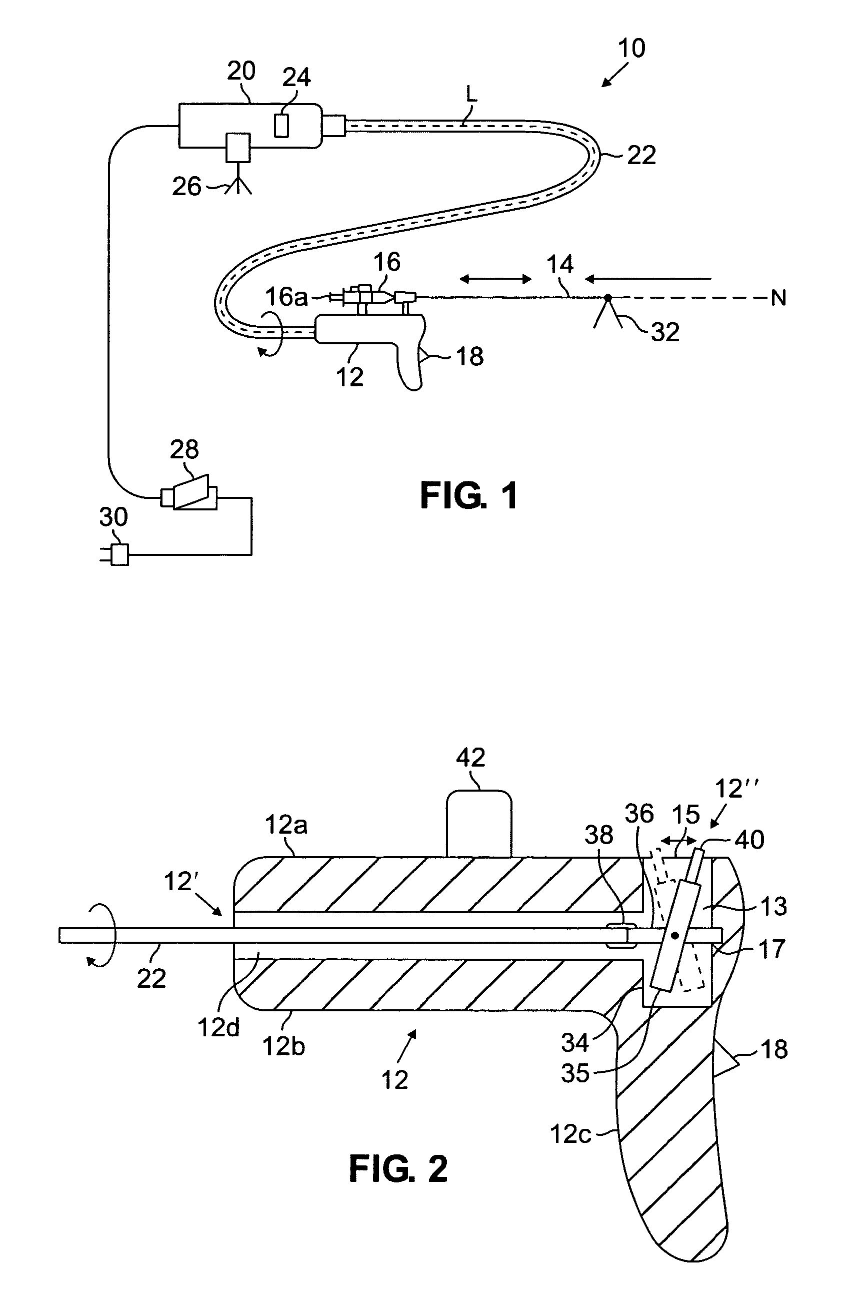
[0027]FIG. 1 shows a biopsy needle system 10 in accordance with a preferred embodiment of the present invention. The system includes a vibration assisted needle device 11 including a needle 14 and a syringe 16. The syringe 16 includes a plunger 16a. Withdrawal of the plunger when the needle is at or within the target tissue provides suction for drawing tissue into the bore of the needle 14. The needle may be connected to a suction or vacuum pump, as well. The device 11 may include a trigger 18 for activating a drive mechanism for causing vibration of the needle 14.

[0028]In this embodiment of the invention, the drive mechanism is a rotating device, such as a drill 20. The drill 20 may be connected to the device 11 through a flexible shaft 22. Rotation of the drill 20 causes rotation of the shaft 22 about its longitudinal axis “L”, shown in phantom extending through the center of the shaft 22 in FIG. 1, resulting in the reciprocation of the needle 14 along its longitudinal axis “N”, a...


PUM


Abstract

A vibration assisted needle device is disclosed for use in medical procedures such as needle aspiration biopsies. Reciprocation of the needle, such as a biopsy needle, eases the advance of the needle through tissue, penetration of the site of interest and the collection of sample at a site of interest. The device comprises a housing defining a chamber, a needle support external to the chamber for supporting a needle and a mechanism in the chamber for causing reciprocatory motion of the needle support. The needle support is preferably external to the housing. A syringe support may be connected to the housing for supporting a syringe. The reciprocatory mechanism may comprise means for converting rotational motion into reciprocating motion, such as a bearing or a rotor with a circumferential, angled groove on its surface, coupled to the needle support. The bearing or the rotor may be driven by a rotational motor, preferably located outside of the housing, or by a hydraulically driven turbine within the housing. Alternatively, the reciprocatory mechanism means may comprise a stationary solenoid and a movable solenoid for being coupled to the needle. Preferably, a second stationary solenoid is provided and the moving solenoid is between the two stationary solenoids. Energization of the stationary solenoid or solenoids by an alternating current for example, and energization of the movable solenoid by a direct current, or vice versa, attracts and repulses the movable solenoid, causing reciprocation of the needle. Methods and systems using the vibration assisted needle device are also disclosed.

Description

[0001]This application is a continuation of application Ser. No. 09 / 799,926, filed on Mar. 6, 2001, which issued on Mar. 9, 2004 bearing U.S. Pat. No. 6,702,761 B1, which claims the benefit of provisional appl. 60 / 187,261 filed on Mar. 6, 2000, is assigned to the assignee of the present invention and is incorporated by reference, herein.FIELD OF THE INVENTION[0002]A needle device, and more particularly, a biopsy needle device which is driven to vibrate in a direction along the axis of the needle to ease passage of the needle through tissue and the collection of a sample at a site of interest.BACKGROUND OF THE INVENTION[0003]When an abnormal area of tissue, such as a tumor, is discovered by non-invasive means, a tissue diagnosis is often required in order to determine the appropriate treatment. This requires that an adequate sample of tissue be removed from the patient for histopathological analysis. The tissue may be obtained in a variety of ways, such as surgical excision, fine nee...

Claims


Application Information

Patent Timeline
Patent Type & Authority Patents(United States)
IPC IPC(8): A61B5/00A61B10/00A61B10/02A61B17/00A61B18/00
CPCA61B10/0233A61B2018/00196A61B2017/00544
Inventor DAMADIAN, JEVANVOTRUBA, JANGELBIEN, MARK
Owner FONAR
Learn More