
Parallel computer having a hierarchy structure

a computer and hierarchy technology, applied in the field of parallel computers, can solve the problems of reducing the performance of the computer system, increasing the delay of the signal transfer on the bus, and increasing the execution time of the transaction

Inactive Publication Date: 2006-01-26
KK TOSHIBA
View PDF10 Cites 14 Cited by
  • Summary
  • Abstract
  • Description
  • Claims
  • Application Information

AI Technical Summary

Benefits of technology

[0014] Accordingly, an object of the present invention is, with due consideration to the drawbacks of the conventional technique, to provide a parallel computer

Problems solved by technology

The common bus structure, however, has several drawbacks to light the feature of the multi-processing computer system.
This reduces the performance of the computer system.
When the capacity load and the length of the bus are increased, the delay of the signal transfer on the bus is also increased.
The increasing of the delay of the signal transfer also causes the increasing of the execution time of a transaction.
Accordingly, the bus having the adequate bandwidth for a multiprocessing computer system in a previous generation can not satisfy the demand of a current computer system including processors of a high performance.
Further, there is a drawback that it becomes difficult to make a programming model and to perform a debug the multi-processing systems other than the systems having the common bus structure.

Method used


Image

  • Parallel computer having a hierarchy structure
  • Parallel computer having a hierarchy structure
  • Parallel computer having a hierarchy structure

Examples


first embodiment

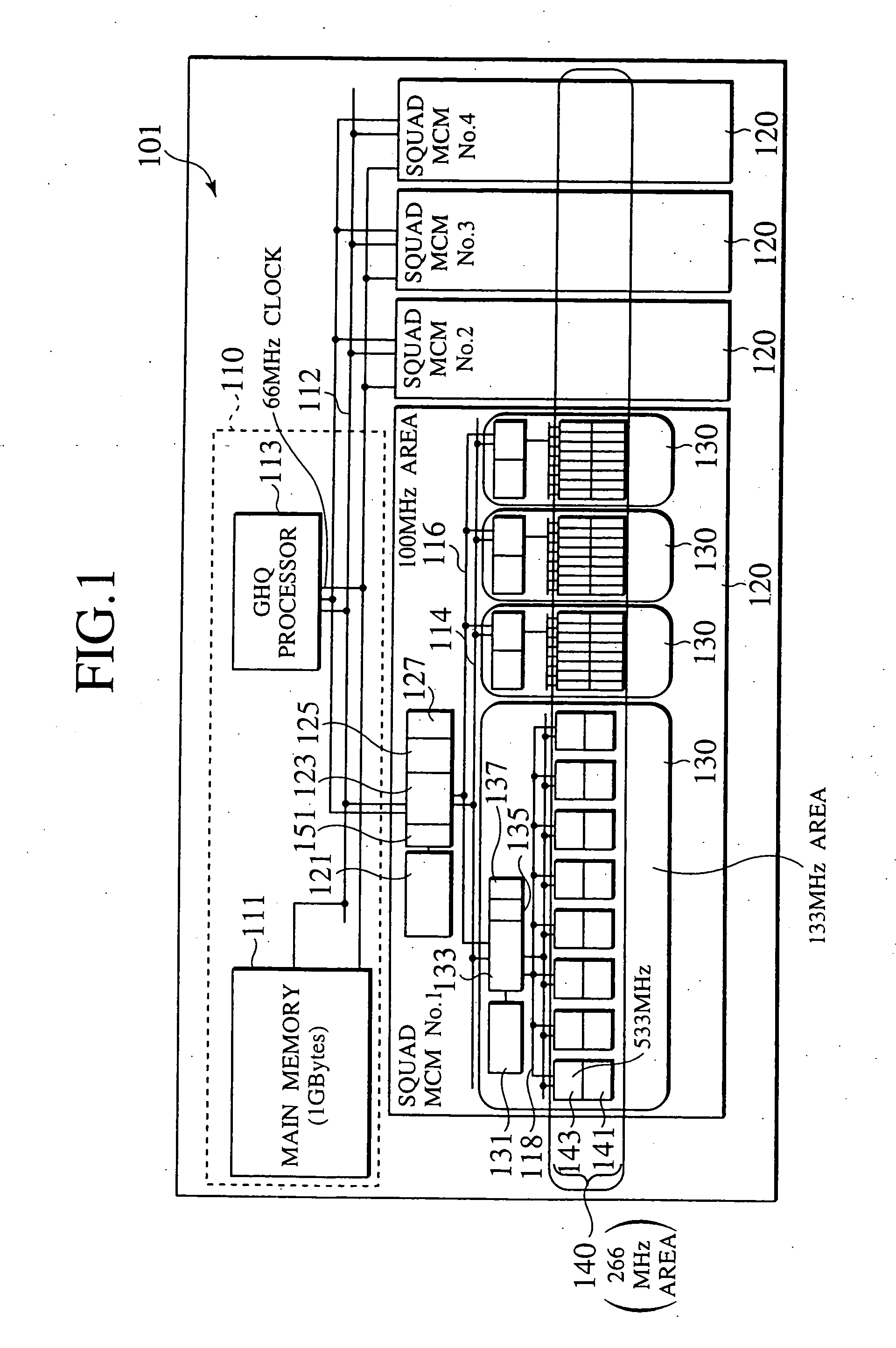
[0051]FIG. 1 is a block diagram showing an overview of a multiprocessor system having a hierarchy bus structure according to a first embodiment as the parallel computer having a hierarchy structure of the present invention.

[0052] The multiprocessor system having a hierarchy bus structure shown in FIG. 1 comprises a GHQ main memory of 1 Gbytes, a GHQ processor 113, and four SQUAD processing units 120 each of which incorporates a plurality of processors (that will be described later in detail). Each SQUAD processing unit 120 is implemented with a multi-chip module (MCM). The GHQ processor 113, the four SQUAD processing units 120, and the GHQ main memory 111 are connected through a first level bus 112.

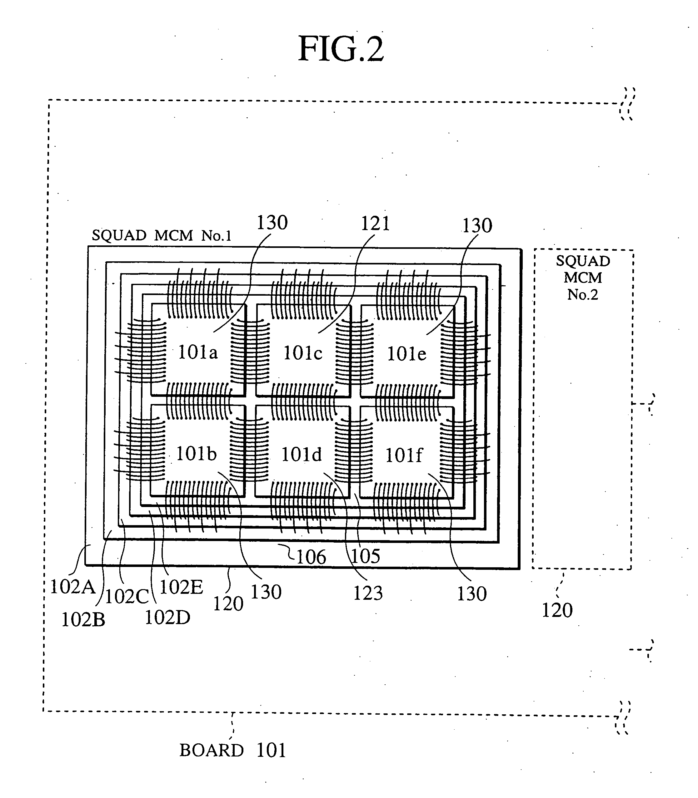
[0053] The six component units, namely, a memory module forming the GHQ main memory 111, the GHQ processor 113, and the four MCMs are connected to each other on a print wiring board 101. As shown in FIG. 2, each of the four SQARD processing units 120 is mounted as the MCM on the pint wi...

second embodiment

[0105]FIG. 3 is a block diagram showing an overview of a multiprocessor system having a hierarchy bus structure as the parallel computer having a hierarchy structure according to the second embodiment of the present invention.

[0106] The multiprocessor system of a hierarchy bus structure shown in FIG. 3 comprises a GHQ main memory of 1 Gbytes formed on a single semiconductor chip, a GHQ processor 213 formed on a single semiconductor chip, and four SQUAD processing units 220 each of which incorporates a plurality of processors (that will be described in detail). Each SQUAD processing unit 220 is formed on a single semiconductor chip.

[0107] The GHQ processor 213, the four SQUAD processing units 220, and the GHQ main memory 211 are connected through a first level bus 212.

[0108] The six component units, namely, a memory module forming the GHQ main memory 211, the GHQ processor 213, and the four SQUAD processing units 220 are mounted on a single multichip module (MCM). In general, the ...


PUM


Abstract

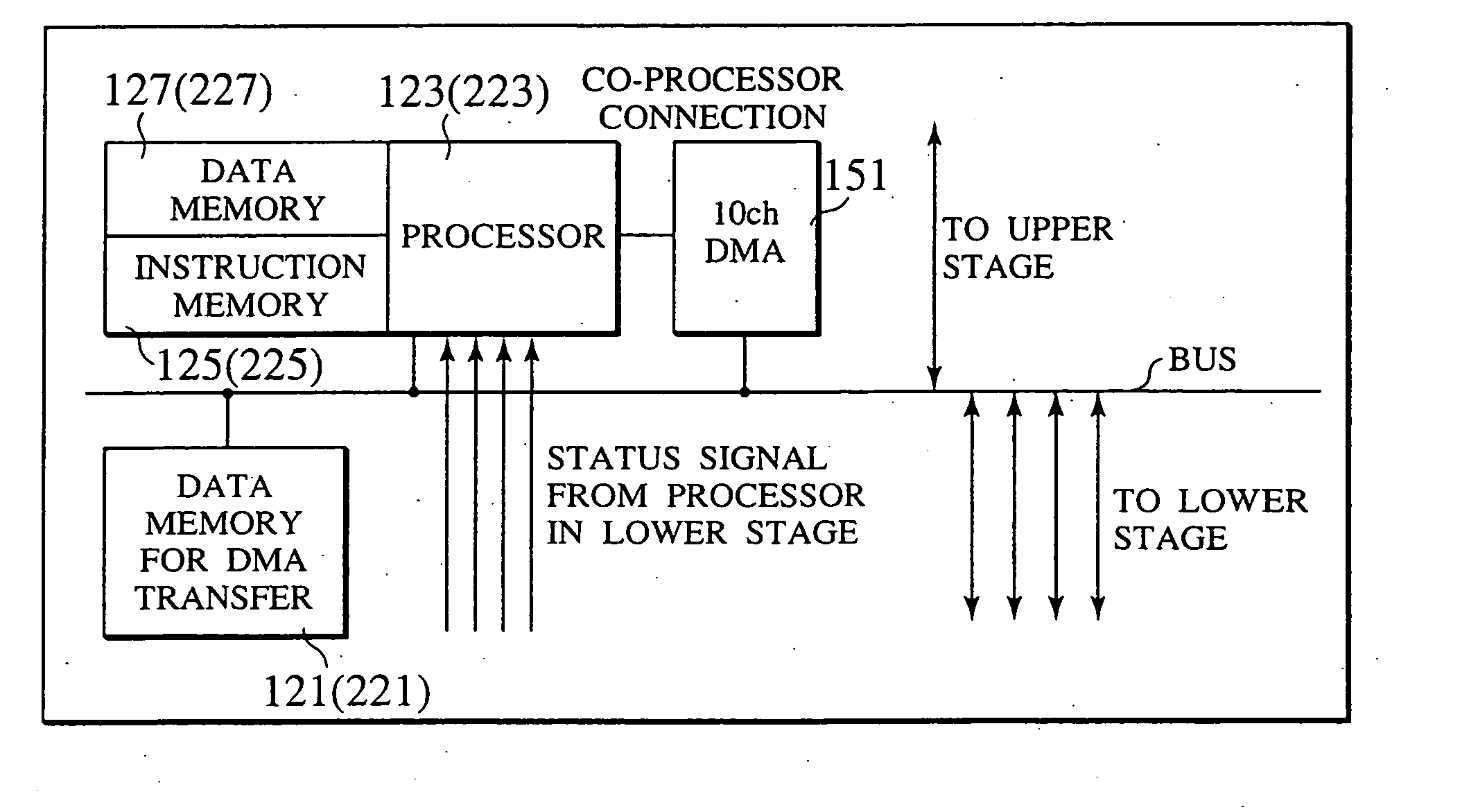
In a multiprocessor system of a hierarchy configuration as a parallel computer of a common-bus structure, a processing unit (120) in an intermediate stage has a processor (123) having a programmable function that is equal to a normal processor, an instruction memory (125), and a data memory (127). The processing unit (120) receives a status signal from a lower processor (143), and a DMA controller (151) having a memory for the transfer of large sized data performs compression, decompression, programmable load dispersion, and load dispersion according to the state of operation of each lower processor.

Description

CROSS-REFERENCE TO RELATED APPLICATION [0001] This application is based upon and claims the benefit of priority from the prior Japanese Patent Application No.11-297439, filed Oct. 19, 1999; the entire contents of which are incorporated herein by reference. BACKGROUND OF THE INVENTION [0002] 1. Field of the Invention [0003] The present invention relates to a parallel computer having a hierarchy structure, and more particularly, to a parallel computer that may be most applied to image processing that requires enormous amount of calculation, computer entertainments, and execution of scientific calculations. [0004] 2. Description of the Related Art [0005] In conventional parallel computers, for instance, a conventional parallel computer having a common bus structure (or a common bus system), a plurality of processors implemented with a plurality of semiconductor chips are arranged through a common bus formed on a semiconductor substrate. In this configuration, in order to further reduce...

Claims


Application Information

Patent Timeline
IPC IPC(8): G06F15/00G06F9/50G06F15/173G06F13/36G06F15/177G06F15/80
CPCG06F15/8007G06F9/5066G06F13/36
Inventor KUNIMATSU, ATSUSHIWATANABE, YUKIOYASUKAWA, HIDEKI
Owner KK TOSHIBA
Learn More