
Method and apparatus for multiprocessor debug support

a multi-processor and debugging technology, applied in the field of debugging, codevelopment and covalidation of software, can solve problems such as system delay, general infrastructure support, and speed of debugging

Inactive Publication Date: 2005-10-27
INTEL CORP
View PDF7 Cites 36 Cited by
  • Summary
  • Abstract
  • Description
  • Claims
  • Application Information

AI Technical Summary

Benefits of technology

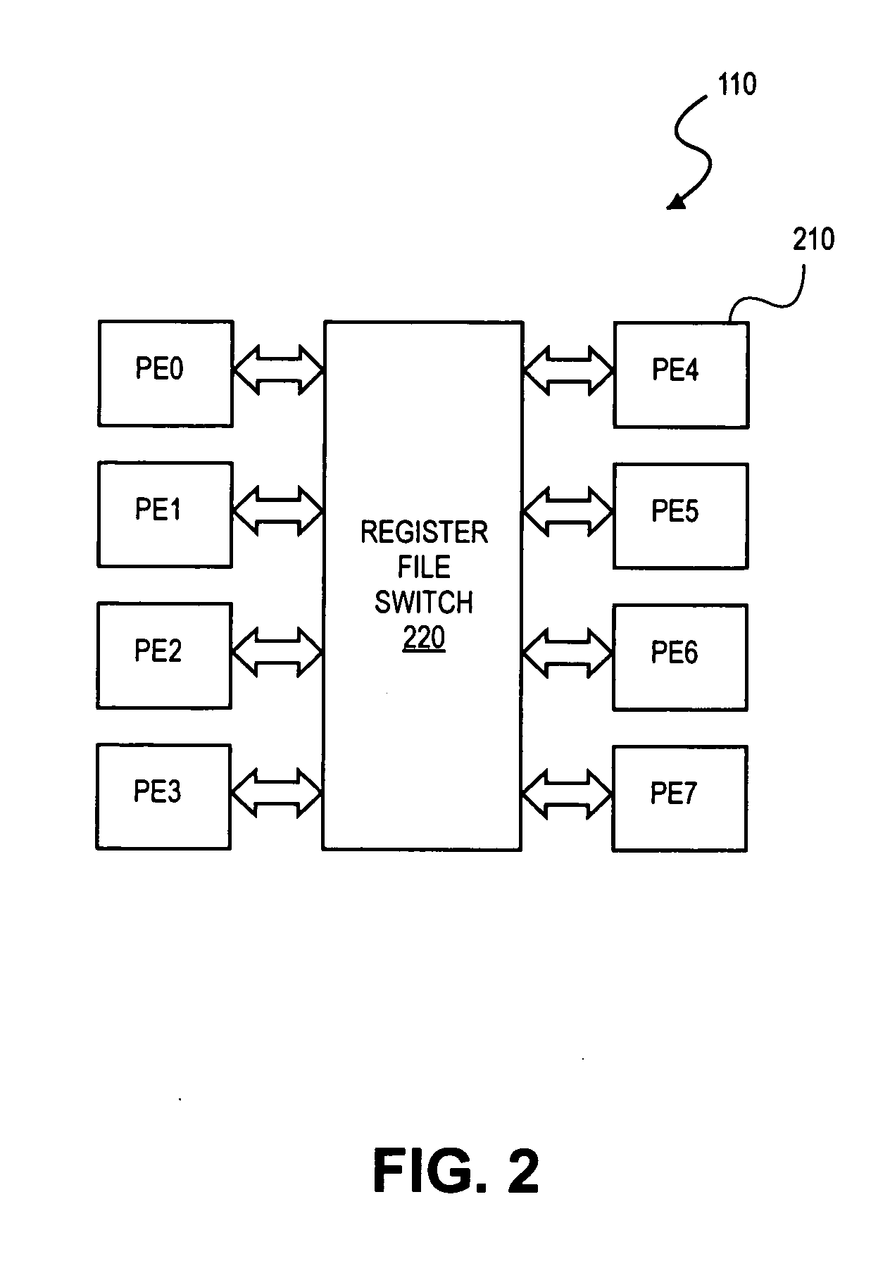
The patent text describes a method and apparatus for debugging software in a multiprocessor environment. The technical effects of the patent include real-time debugging, co-development, and co-validation of software. The method involves embedding debug functions in a multiprocessor chip to assist developers with product implementation and validation. The chip includes processing elements and a register file switch for efficient interconnect and data flow. The method also includes a memory command handler for data processing and a data driven mechanism for data validity. The patent text provides a detailed description of the debugging environment and the various components and functions involved in the process.

Problems solved by technology

One of the problems with scan-based debugging is that it generally requires infrastructure support.
Another problem with scan-based debugging is the speed of debugging, i.e. system delay caused by debugging.

Method used


Image

  • Method and apparatus for multiprocessor debug support
  • Method and apparatus for multiprocessor debug support
  • Method and apparatus for multiprocessor debug support

Examples


Embodiment Construction

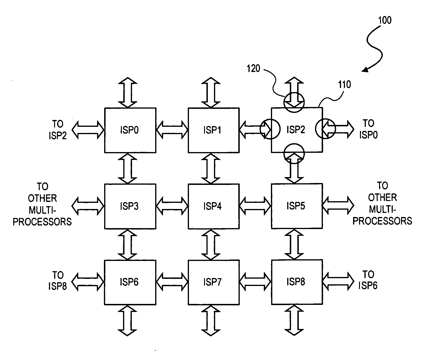
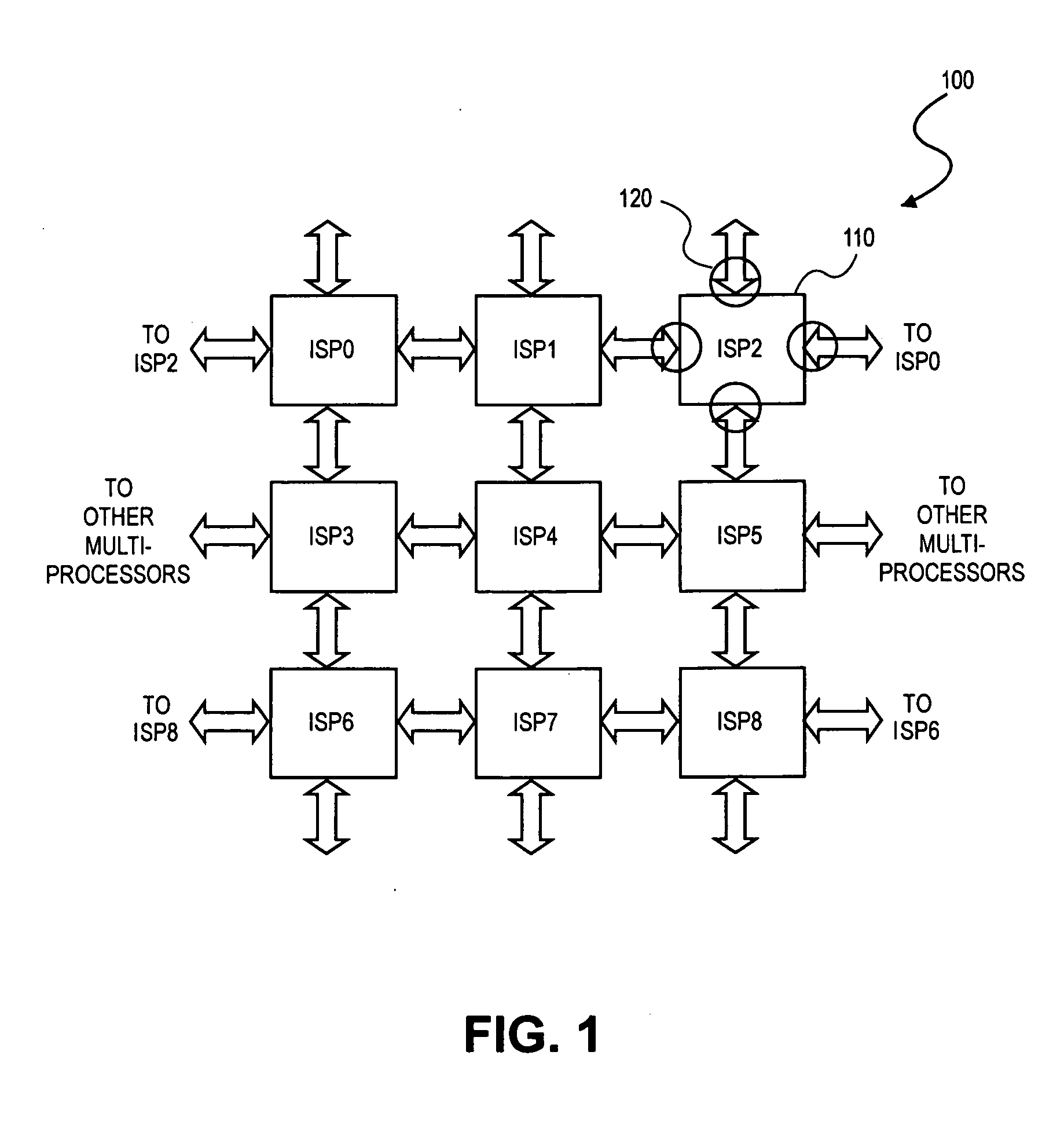
[0018] The embodiments discussed herein generally relate to a method and apparatus for debugging a multiprocessor environment. Referring to the figures, exemplary embodiments will now be described. The exemplary embodiments are provided to illustrate the embodiments and should not be construed as limiting the scope of the embodiments.

[0019] Reference in the specification to “an embodiment,”“one embodiment,”“some embodiments,” or “other embodiments” means that a particular feature, structure, or characteristic described in connection with the embodiments is included in at least some embodiments, but not necessarily all embodiments. The various appearances “an embodiment,”“one embodiment,” or “some embodiments” are not necessarily all referring to the same embodiments. If the specification states a component, feature, structure, or characteristic “may”, “might”, or “could” be included, that particular component, feature, structure, or characteristic is not required to be included. If...


PUM


Abstract

A device having at least one processor connected a controller and a memory; where the controller to execute a debug process. The debug process attaches a breakpoint bit field to each instruction. A system having image signal processors (ISPs), each ISP including processor elements (PEs). The ISPs include a debug instruction register connected to a first mux element. An instruction memory is connected to an instruction register. A decoder is connected to the instruction register. An execution unit is connected to the decoder. A debug executive unit is connected to the instruction memory, and a second mux element is connected to the execution unit and local registers. The decoder decodes a breakpoint bit field of each instruction.

Description

BACKGROUND [0001] 1. Field [0002] The embodiments relate to debugging, co-development and co-validation of software, and more particularly to real-time debugging, co-development and co-validation of software within a multiprocessor environment. [0003] 2. Description of the Related Art [0004] With processing systems today one commonly used approach for implementing hardware debugging features is known as scan-based debugging. In scan-based debugging an internal state is scanned in / out to obtain controllability and visibility into the system. Typically, scan-based debugging is used in silicon implementations. One of the problems with scan-based debugging is that it generally requires infrastructure support. Another problem with scan-based debugging is the speed of debugging, i.e. system delay caused by debugging.BRIEF DESCRIPTION OF THE DRAWINGS [0005] The embodiments of the invention are illustrated by way of example and not by way of limitation in the figures of the accompanying dra...

Claims


Application Information

Patent Timeline
Patent Type & Authority Applications(United States)
IPC IPC(8): G06F11/00
CPCG06F11/3648
Inventor VANNERSON, ERIC F.MEHTA, KALPESH D.CHEN, ERNEST P.
Owner INTEL CORP
Learn More