
Method and device for producing optical material, and an optical waveguide

a technology of optical material and optical waveguide, which is applied in the direction of glass deposition burners, combustion types, lighting and heating apparatuses, etc., to achieve the effects of reducing the formation of erbium ion clusters, reducing the production capacity of the device and the method according to the present invention, and improving the homogeneity of the produced particles

Inactive Publication Date: 2006-01-05
LIEKKI OY
View PDF31 Cites 28 Cited by
  • Summary
  • Abstract
  • Description
  • Claims
  • Application Information

AI Technical Summary

Benefits of technology

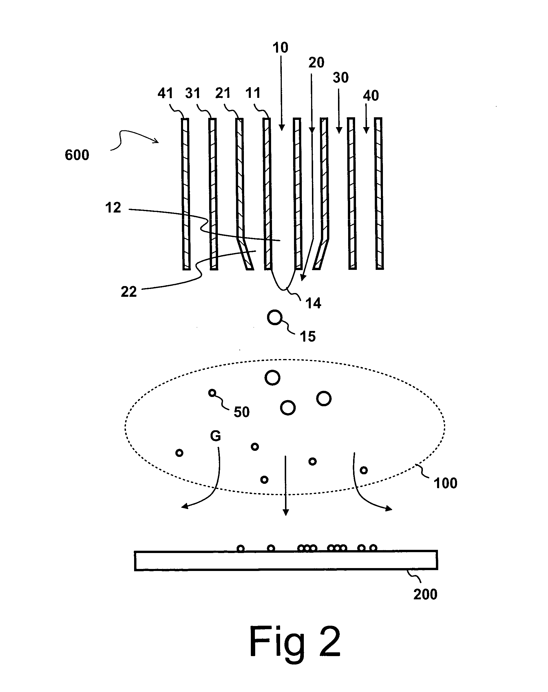
[0014] By applying a high velocity of the atomizing gas several advantageous effects take place: The average size of the atomized droplets becomes small thanks to the high velocity of the atomizing gas. The atomized droplets are rapidly transferred to the flame. The high velocity of the atomizing gas enhances turbulence and mixing of the reactants in the flame. Thanks to effective mixing the reaction rates are high. The high rate of combustion leads to high combustion temperature, which further accelerates the rates of oxidation and doping reactions and accelerates gas velocity in the flame. Thanks to the high temperature and small droplet size, the droplets are evaporated rapidly in the flame. The dimensions of the flame are shrunk thanks to the high reaction rates. Turbulence enhances also mixing of cold gas to the reaction gases reducing the effective residence times even further. Thanks to the high gas velocity and small dimensions, the residence time of the substances in the flame are reduced. The low residence times reduce the agglomeration of the droplets and the produced particles.
[0015] The turbulent flame is not sensitive to disturbances. Therefore the production capacity of the device and the method according to the present invention can be scaled up by arranging several devices to operate adjacent to each other.
[0016] The residence time of the reaction products in the flame is short. Thus particles comprising nonequilibrium chemical products can be produced. For example, the separation of different phases in the produced material and the undesired clustering of erbium ions are minimized, which improves the homogeneity of the produced particles.
[0017] This is advantageous especially in the production of particles suitable for manufacturing of light-amplifying optical waveguides. For example, in case of doping with erbium, the aim is to have single and isolated erbium ions in the material. Clustered forms of erbium are not effective in the amplification of light. Erbium has a tendency to form Er2O3 in the gas phase, if sufficient time is available to reach thermodynamical equilibrium. In an Al—Si—O system erbium has a tendency to form Al5Er3O12.Al2O3, respectively. According to the invention, the formation of the erbium ion clusters can be minimized by limiting the residence time of the particles in the flame, which is achieved by applying the high velocity of the atomizing gas.
[0018] Because the clustering of the active ions is substantially minimized, it is possible to increase the concentration of said ions in the produced light-amplifying material, which consequently leads to high quantum conversion efficiency. Thus, erbium-doped optical waveguide produced according to the present invention has excellent light-amplifying characteristics. For example, an Er-doped fiber produced according to the present invention was found to provide a quantum conversion efficiency of 65%.

Problems solved by technology

It is known that high gas velocities induce turbulence, which in turn is associated with chaotic spatial and temporal variations of temperature and local gas composition.

Method used


Image

  • Method and device for producing optical material, and an optical waveguide
  • Method and device for producing optical material, and an optical waveguide
  • Method and device for producing optical material, and an optical waveguide

Examples


Embodiment Construction

[0033] The device for making light-amplifying optical material comprises at least a burner assembly, which is used for producing particles of erbium-doped silica glass.

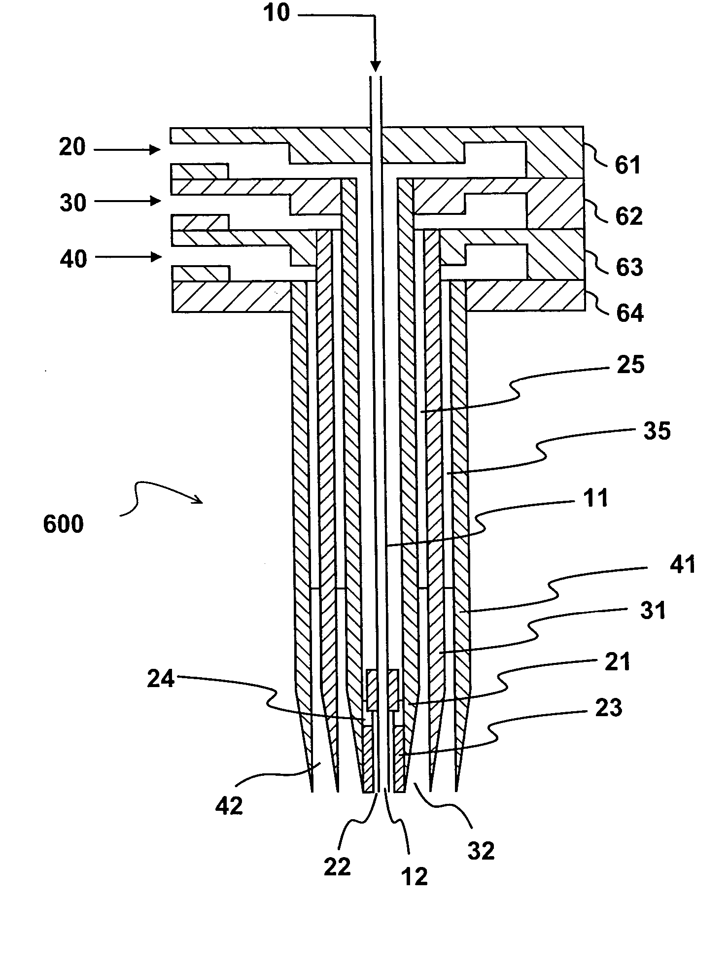
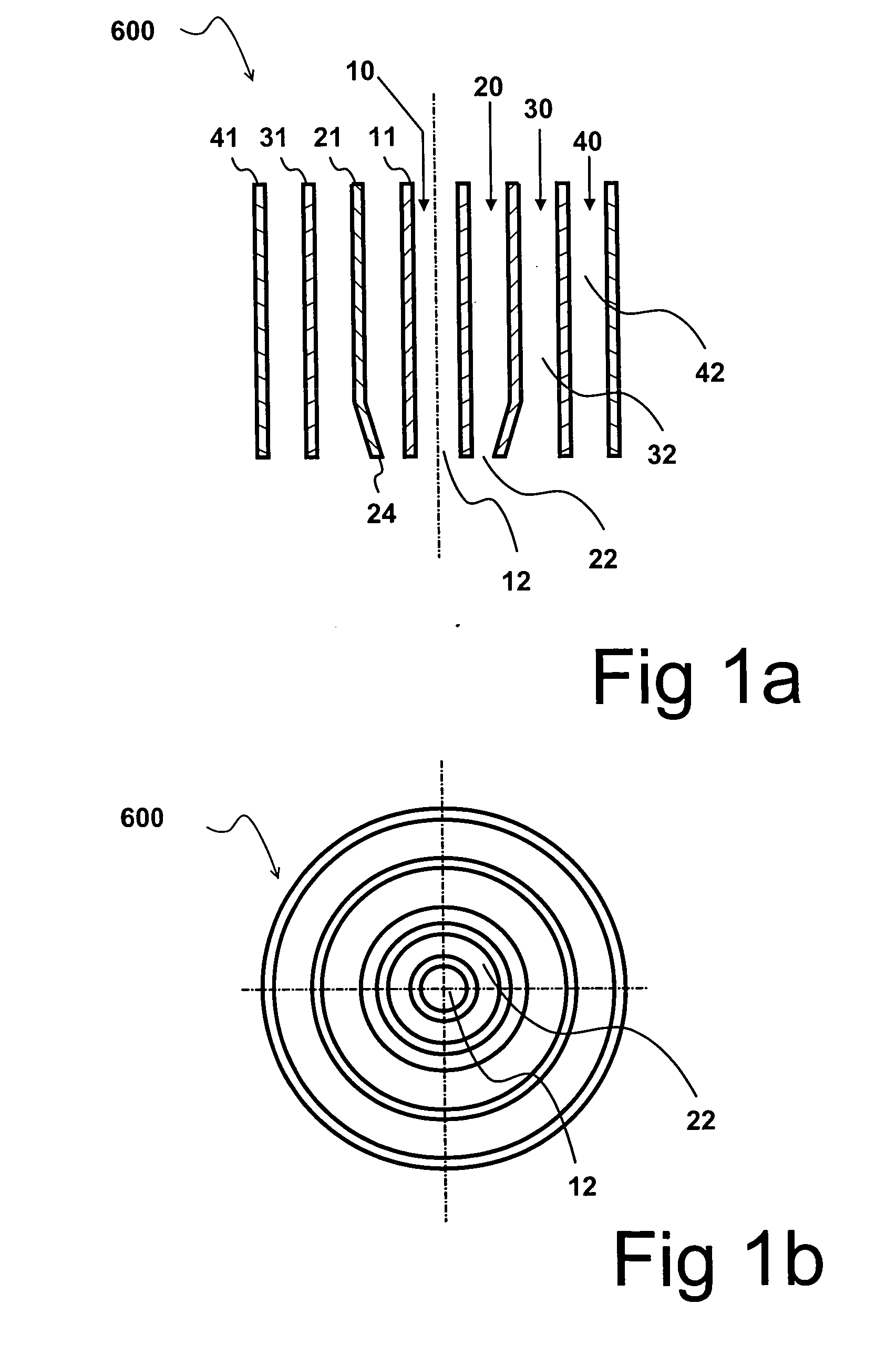
[0034] Referring to FIGS. 1a and 1b, the burner assembly 600 comprises four tubes 11, 21, 31, 41, which define four concentric nozzles 12, 22, 32, 42. The innermost nozzle, herein called as the liquid nozzle, is used for delivering liquid reactant 10. The outer surface of the tube 11 and the inner surface of the tube 21 define together an annular atomizing gas nozzle 22, from which an atomizing gas 20 is discharged. The atomizing gas is accelerated by a pressure difference prevailing over the nozzle 22. The velocity of the atomizing gas 20 may be further accelerated by the constriction 24 of the nozzle 22. Instead of the constriction 24 of the tube 21, the cross-section may also be reduced by implementing an enlargement of the outer surface of the liquid reactant tube 11. The burner assembly 600 may also comprise mor...


PUM

PropertyMeasurementUnit
velocityaaaaaaaaaa
velocityaaaaaaaaaa
Gas flow rateaaaaaaaaaa

Abstract

The invention relates to the production of light-amplifying optical material. Liquid reactant is atomized into droplets using a high velocity gas. The droplets are subsequently introduced into a flame. Reactants are oxidized in the flame and condensed by forming small particles. At least a fraction of said particles is collected and fused to form optical waveguide material, which is subsequently drawn to form an optical waveguide. According to the invention, the velocity of the atomizing gas stream is in the order of the velocity of sound. The high velocity enhances atomization and increases reaction rates in the flame. The residence times are reduced to such a degree that unwanted phase transformations in the produced particles are substantially minimized. Consequently, very homogeneous material is produced. Especially, in the production of erbium-doped silica, low percentage of clustered erbium ions is achieved.

Description

[0001] The present invention relates to a method for producing light-amplifying optical material, said method comprising at least atomizing at least one reactant in liquid form by an atomizing gas to form droplets, introducing said droplets and / or their vaporous products into a flame, oxidizing said at least one reactant to form one or more, condensing said one or more oxides to produce particles, collecting at least a part of said particles, and fusing said particles together to form said light-amplifying optical material. The present invention relates also to a device for producing said light-amplifying optical material and to an optical waveguide comprising said light-amplifying optical material. BACKGROUND OF THE INVENTION [0002] Generation of small particles is an important step in the production of light-amplifying optical waveguides, which amplify light by stimulated emission of radiation. The light-amplifying properties of those waveguides are achieved by doping, for example...

Claims


Application Information

Patent Timeline
Patent Type & Authority Applications(United States)
IPC IPC(8): H01S3/00C03B37/014C03C13/04F23D11/10F23D11/38F23D14/32F23D14/52F23D14/70G02B6/02G02B6/12
CPCC03B37/0142C03B2201/34C03C3/06C03B2207/14C03B2207/34C03B2201/36C03B37/014C03C13/04C23C4/12F23D11/10Y02P40/57
Inventor JANKA, KAUKORAJALA, MARKKUTIKKANEN, JUHA
Owner LIEKKI OY
Learn More