
Erbium-doped fiber amplifier and integrated circuit module components

a fiber amplifier and integrated circuit technology, applied in the field of fiberoptic systems and networks, can solve the problems of polarization-dependent gain (pdg), the cost of edfas today is still high, and the use is still difficult, so as to improve the coupling efficiency of laser diodes, and improve the effect of numerical apertur

Inactive Publication Date: 2005-12-22
LIGHTWAVES 2020
View PDF14 Cites 10 Cited by
  • Summary
  • Abstract
  • Description
  • Claims
  • Application Information

AI Technical Summary

Benefits of technology

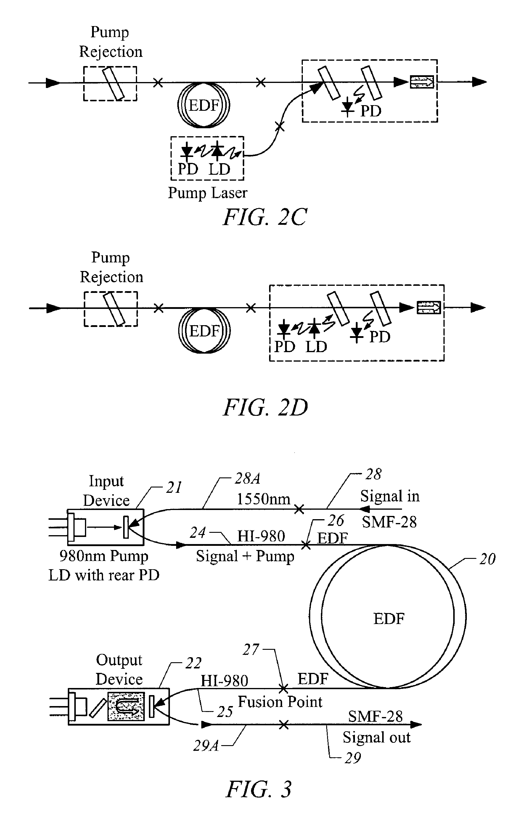
"The present invention provides an EDFA system for amplifying optical signals in a small package. The system includes an erbium-doped optical fiber section and a laser diode for pumping the fiber. The system also has a WDM filter and a collimating lens for efficient coupling of the laser diode to the fiber section. The output module has many features for monitoring and isolating the fiber section. The system is relatively inexpensive and easy to mount."

Problems solved by technology

Nonetheless, EDFAs today are still expensive and are used primarily in the so-called “long-haul” or “backbone” fiberoptic networks which link nodes over long, intra-continental and even inter-continental, distances.
Most of these fibers have been laid and the present challenge to fiberoptic developers are the “metro-,” i.e., citywide, or smaller, networks.
However, wideband EDFA is quite expensive for some applications, such as metro-networks and power compensation.
SOAs have disadvantages of high noise figures, polarization-dependent gain (PDG) and cross talk; their applications are very limited.
Likewise, EDWAs require very high pump power to provide sufficient gain and output power, while their noise figures are quite high.

Method used


Image

  • Erbium-doped fiber amplifier and integrated circuit module components
  • Erbium-doped fiber amplifier and integrated circuit module components
  • Erbium-doped fiber amplifier and integrated circuit module components

Examples


Embodiment Construction

[0019] To amplify optical signals carried on an optical fiber, the optical fiber is severed and an EDFA is inserted between the two parts of the optical fiber. Optical signals are typically in the 1550 nm wavelength range; for WDM systems, the signals fall within specific wavelength ranges which define a grid of WDM communication channels. The EDFA increases the strength of these signals at their particular wavelengths.

[0020]FIG. 1 illustrates the general features, organization and operation of an EDFA between two parts 18 and 19 of an optical fiber carrying signals. The EDFA is formed by a section 10 of erbium-doped fiber, which amplifies the optical signals passing through the section 10. To provide the amplification energy for the EDF section 10, an optical pump in the form of a laser 11 is connected to one end of the section 10 by a WDM (Wavelength Division Multiplexer) 12. The WDM 12 is connected to the input optical fiber 18 which carries the optical signals into the EDFA and...


PUM


Abstract

An EDFA with integrated input and output modules is presented. The integrated input module has a packaged pump laser diode mounted to the metal EDFA package to provide a heat sink for the pump laser diode which sends the pump laser light over a optical fiber section connected to the amplifying erbium-doped optical fiber section. The fiber section is formed from an optical fiber which better matches the transmission modes in the erbium-doped optical fiber section and has an end subsection of the single mode fiber for a larger numerical aperture. Collimating lenses also increase the coupling efficiency of the laser diode to the erbium-doped fiber section. The integrated output module has a photodiode with a tap filter to monitor the output power of the EDFA, an optical isolator to prevent interference in the erbium-doped optical fiber section. With a twin optical isolator, the integrated input and output modules can be arranged in different ways and combinations with the erbium-doped optical fiber section. The resulting EDFAs can be manufactured relatively inexpensively into an very small packages compared to current EDFA packages.

Description

CROSS-REFERENCES TO RELATED APPLICATIONS [0001] This is a divisional application of U.S. patent application Ser. No. 10 / 138,033 filed May 3, 2002, which is incorporated herein by reference in its entirety.BACKGROUND OF THE INVENTION [0002] The present invention is related to optical devices for fiberoptic systems and networks and, in particular, to erbium-doped fiber amplifiers and their components. [0003] In modern fiberoptic transmission systems and networks, such as Dense Wavelength Division Multiplexing (DWDM) optical networks, the erbium-doped fiber amplifier (EDFA) is employed nearly universally to amplify optical signals. The EDFA provides for optical-to-optical conversion and avoids OEO (Optical-Electrical-Optical) conversion where received optical signals were converted into electrical signals, retimed, reshaped and regenerated back into optical signals. EDFAs have the advantages of wideband, i.e., the ability to amplify signals over a wide range in frequency, high signal g...

Claims


Application Information

Patent Timeline
Patent Type & Authority Applications(United States)
IPC IPC(8): G02B6/26G02B6/32G02B6/34G02B6/42H01S3/067H01S3/094H01S3/0941H01S3/13H01S3/131H01S5/022
CPCG02B6/2746H01S5/0683G02B6/29389G02B6/327G02B6/4201G02B6/4204G02B6/4206G02B6/4208G02B6/4209H01S3/005H01S3/0064H01S3/0078H01S3/06704H01S3/06754H01S3/06766H01S3/094003H01S3/094053H01S3/09415H01S3/1305H01S3/1312H01S3/1608H01S5/0064H01S5/02284H01S5/02296H01S3/1301H01S5/02212G02B6/29361G02B6/4215G02B6/424G02B6/4263G02B6/4269G02B6/4286H01S3/13013H01S5/02251H01S5/02257
Inventor PAN, JING-JONGQIU, XIANGDONGGUAN, KEJIANZHANG, MINGJIE
Owner LIGHTWAVES 2020
Learn More