
Two circuit led light bulb

a technology of led light bulbs and led lamps, which is applied in the direction of semiconductor devices for light sources, lighting and heating apparatus, transportation and packaging, etc., can solve the problems of large heat generation, large power consumption of incandescent vehicle signal-lamps, and relatively short li

Inactive Publication Date: 2005-12-01
LEDTRONICS
View PDF10 Cites 39 Cited by
  • Summary
  • Abstract
  • Description
  • Claims
  • Application Information

AI Technical Summary

Benefits of technology

[0011] The present invention provides an improved LED light bulb for use in brake light bulb socket of an automobile or similar vehicle wherein selected numbers of LED are energized at full intensity depending upon whether the automobile is in the brake light mode on the tail light mode. The light emitting diode lamp includes first and second printed circuit boards having first and second pluralities of light emitting diodes mounted thereupon for emitting monochromatic light in response to power signals supplied from the automobile. The light emitting diode lamp further includes a body adapted to form a bayonet connection, a base having at least one contact, and a support sleeve having a wiring conduit, a support tray, and at least two support stanchions for supporting the first printed circuit board. The light emitting diode lamp also includes an electrical control means electrically connecting the first and second contacts with the first and second printed circuit boards, and a lens cap having a planar front face integrally formed with a cylindrical lens sidewall that terminates in a lens perimeter. The support sleeve supports first and second printed circuit boards in an operable relationship for maximum output of monochromatic light while maintaining high impact resistance. All the LED's are on full intensity in the brake light mode and, via a contact switch in the base, less than the full number of LED's on the first and second printed circuit boards are on at full intensity in the tail light mode, resistors not being required to dim or reduce the intensity of the energized LED's.
[0012] The present invention thus provides an improved vehicle LED light bulb having brake light and tail light modes wherein the manufacturing cost thereof is lowered due to the reduced number of components required to perform those functions.

Problems solved by technology

Incandescent vehicle signal-lamps consume a relatively large amount of power, generate a large amount of heat and have a relatively short life.

Method used


Image

  • Two circuit led light bulb
  • Two circuit led light bulb
  • Two circuit led light bulb

Examples


Embodiment Construction

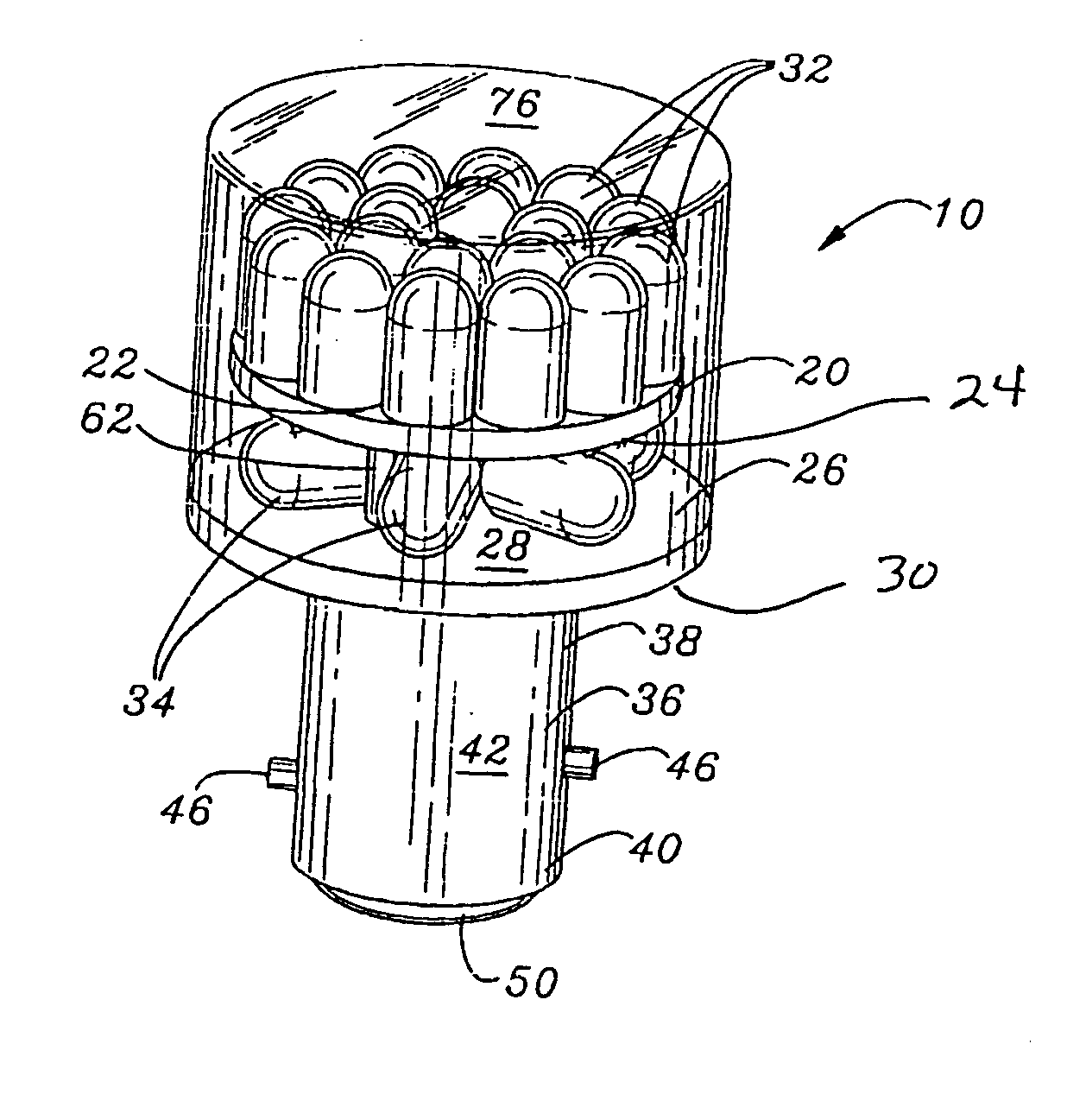
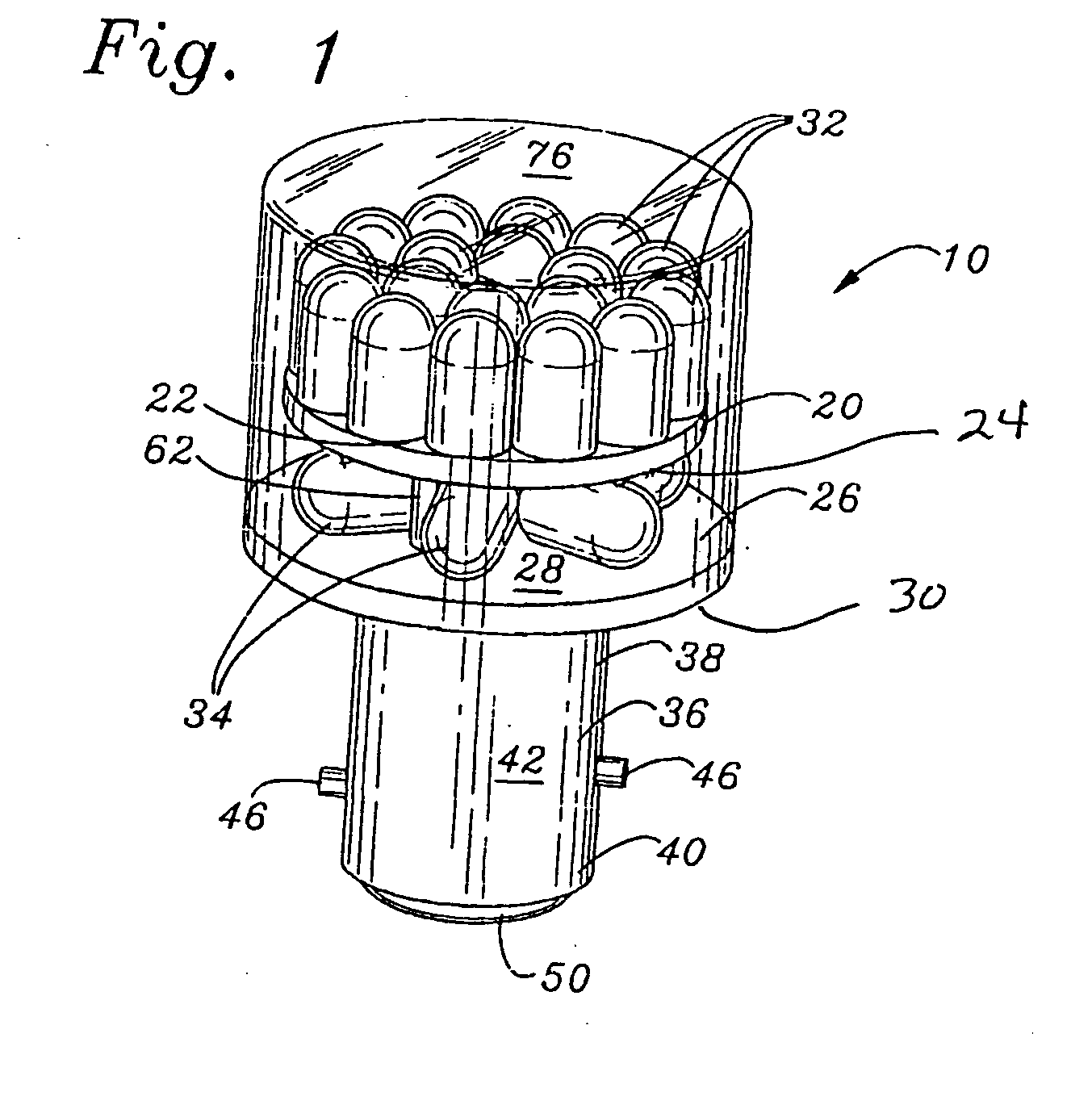
[0019] The present invention provides a light emitting diode lamp 10 for use in a brake light bulb socket (not shown) of an automobile or similar vehicle. In the preferred embodiment, the light emitting diode lamp 10 can be used as both a brake signal and a turn signal.

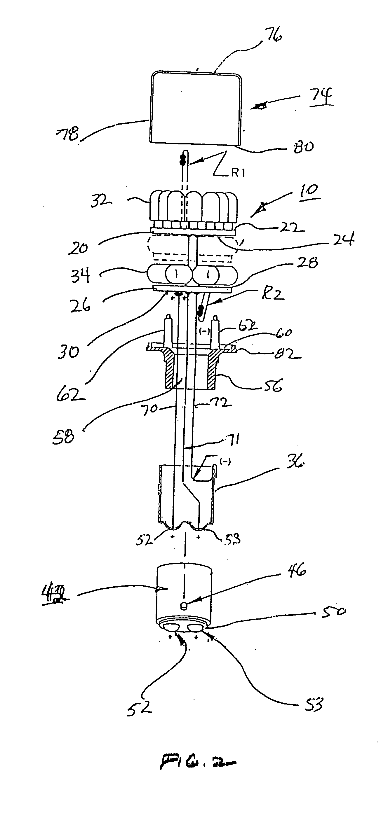
[0020] As shown in FIG. 1, the light emitting diode lamp 10 includes first and second printed circuit boards 20 and 26 having first and second pluralities of light emitting diodes 32 and 34 mounted thereupon for emitting monochromatic light in response to power signals supplied from the automobile. The first printed circuit board 20 has a top surface 22 and a bottom surface 24. The second printed circuit board 26 has a top surface 28 and a bottom surface 30. The first plurality of light emitting diodes 32 is mounted on and generally normal to top surface 22 and electrically coupled with printed circuit board 20. The second plurality of light emitting diodes 34 is mounted on and generally parallel to top surface 28 an...


PUM


Abstract

An improved LED light bulb for use in a brake light bulb socket of an automobile or similar vehicle wherein selected numbers of LED are energized at full intensity depending upon whether the automobile is in the brake light mode or the tail light mode. The light emitting diode lamp includes first and second printed circuit boards having first and second pluralities of light emitting diodes mounted thereupon for emitting monochromatic light in response to power signals supplied from the automobile. All LED's are on full intensity in the brake light mode and less than the full number of LED's on the first and second printed circuit boards are on at full intensity for the tail light mode.

Description

BACKGROUND OF THE INVENTION [0001] 1. Field of the Invention [0002] The present invention provides a two circuit brake, tail and turn signal light emitting diode lamp. [0003] 2. Description of the Prior Art [0004] Light emitting diode lamps have been used to replace incandescent lamps used in automobiles and other motor vehicles and to replace LED lamps for both single filament and dual filament incandescent bulbs. LED's typically operate at voltages between 1.7 and 2.2 volts. [0005] A typical prior art incandescent lamp generally employs a type S-8 glass bulb cemented in a brass bayonet base having dual contacts. A similar incandescent lamp is described in Devir et al., U.S. Pat. No. 4,603,278. Incandescent vehicle signal-lamps consume a relatively large amount of power, generate a large amount of heat and have a relatively short life. [0006] LED lamps designed to replace vehicle incandescent lamps require bases similar to the standard bayonet base. To be effective an LED lamp must...

Claims


Application Information

Patent Timeline
Patent Type & Authority Applications(United States)
IPC IPC(8): B60Q1/26B60Q1/30B60Q1/44B60Q1/56F21K99/00
CPCB60Q1/2607B60Q1/30B60Q1/44F21K9/00F21K9/13F21Y2101/02F21Y2111/008Y10S362/80F21V3/02F21K9/23F21Y2115/10F21Y2107/60
Inventor LODHIE, PERVAIZBECERRA, STEVEN R.
Owner LEDTRONICS
Learn More